Electrical connector capable of suppressing crosstalk

a crosstalk suppression and electric connector technology, applied in the direction of coupling contact members, connection contact material, coupling device connections, etc., can solve problems such as the risk of electrical performance degradation, and achieve the effect of improving electrical performance and reducing crosstalk

Inactive Publication Date: 2007-03-22
JAPAN AVIATION ELECTRONICS IND LTD
View PDF6 Cites 32 Cited by
  • Summary
  • Abstract
  • Description
  • Claims
  • Application Information

AI Technical Summary

Benefits of technology

[0006] It is therefore an object of this invention to provide a connector capable of decreasing crosstalk between adjacent contact groups so that electrical performance is improved.

Problems solved by technology

Accordingly, there is a risk of degradation of electrical performance due to crosstalk between every two adjacent contact groups.

Method used


Image

  • Electrical connector capable of suppressing crosstalk
  • Electrical connector capable of suppressing crosstalk
  • Electrical connector capable of suppressing crosstalk

Examples


Embodiment Construction

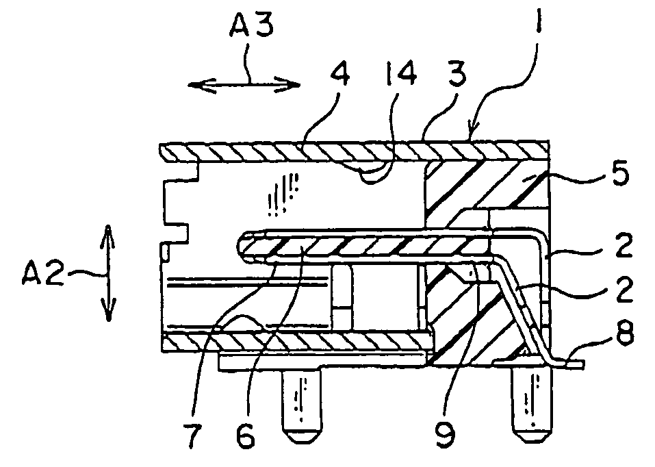
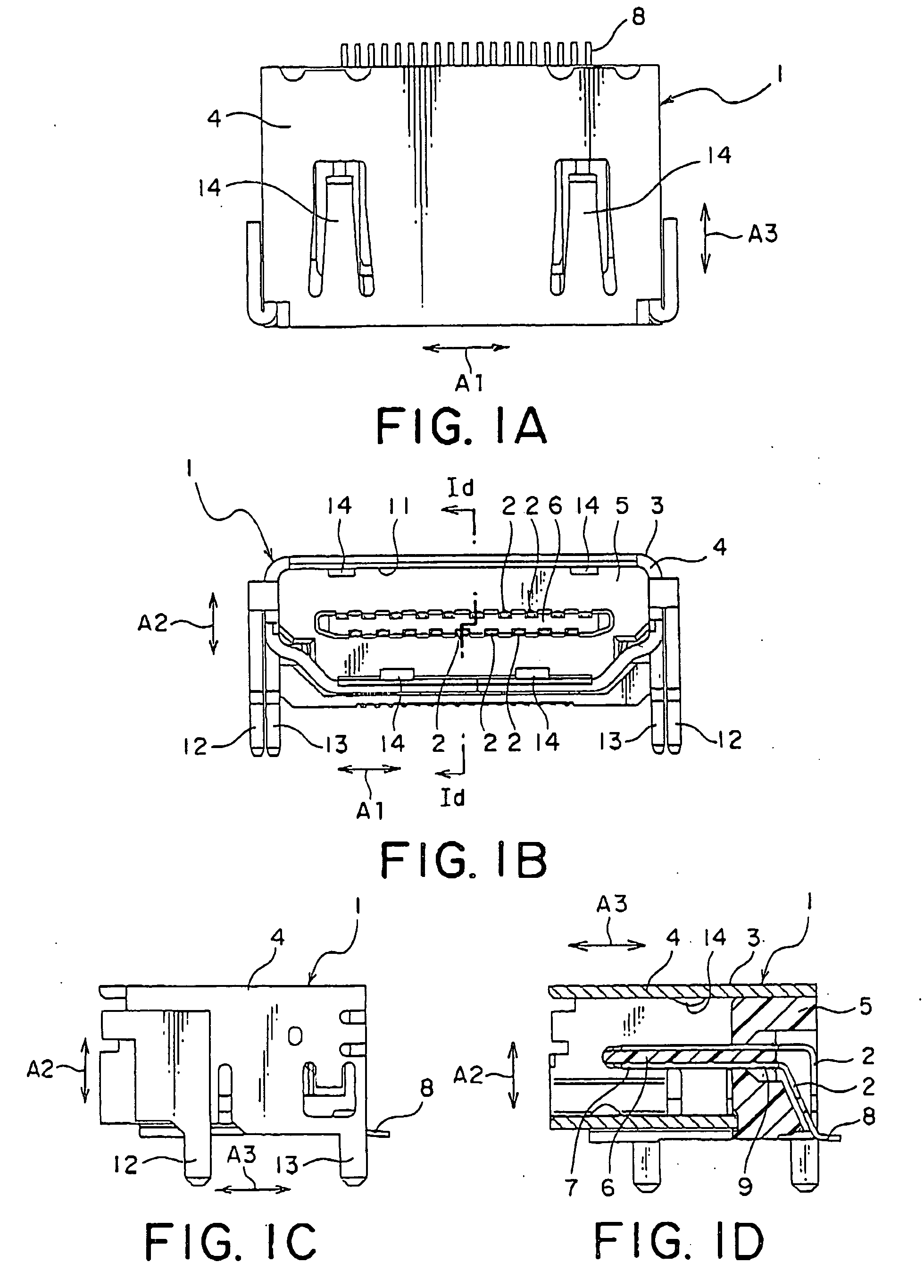
[0020] Referring to FIGS. 1A to 1D, description will be made of a connector according to an embodiment of this invention.

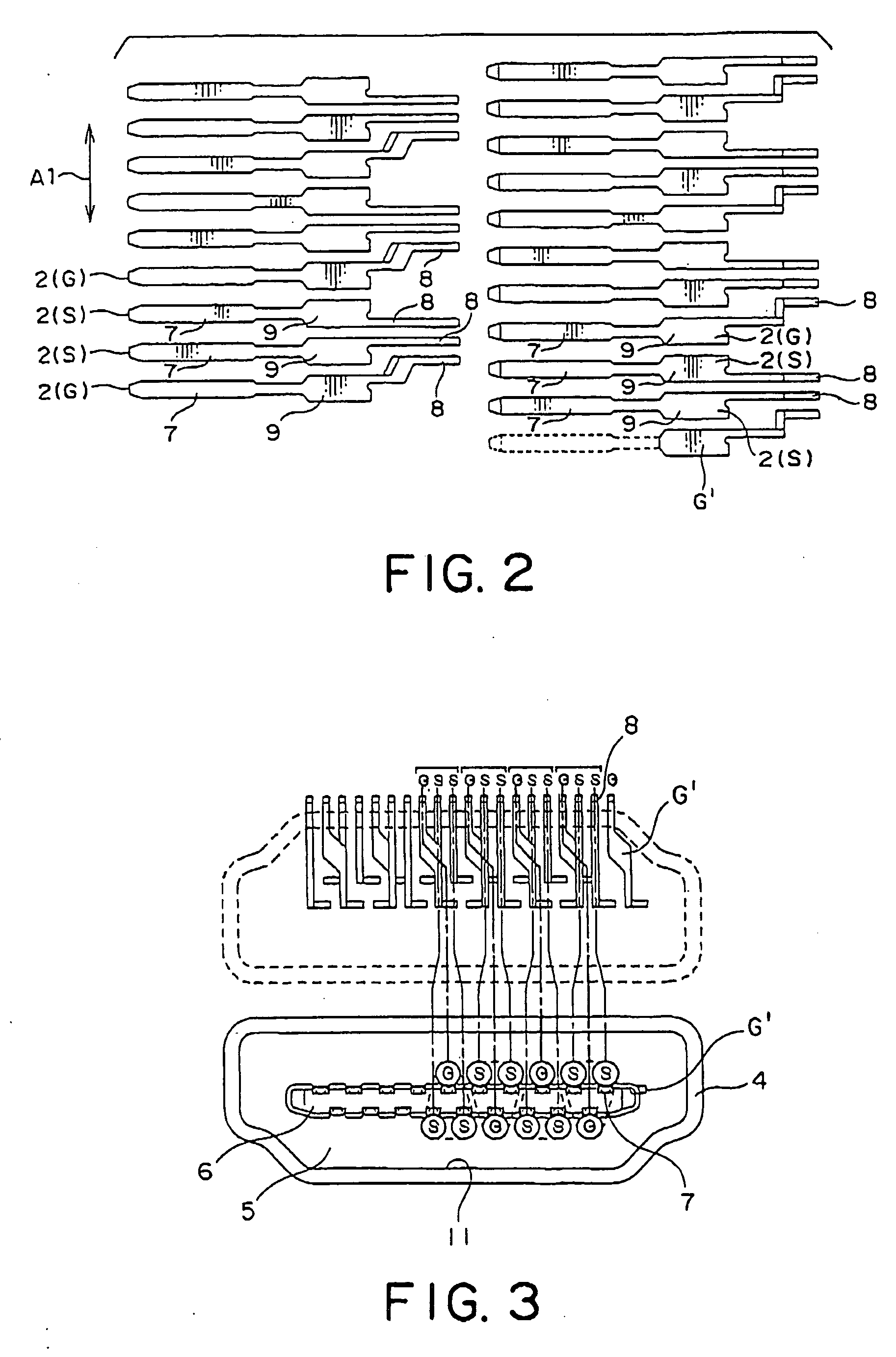
[0021] The connector depicted at 1 in the figure is a receptacle connector called an angle type and suitable for use in high-speed differential transmission, and is mounted to a substrate (not shown). The connector 1 comprises a plurality of conductive contacts 2 and a housing 3 holding the contacts 2. The housing 3 comprises a cylindrical conductive shell 4, a block-like main insulator 5 fixed to the shell 4, and a plate-like subsidiary insulator 6 disposed inside the shell 4 and integrally fixed to the main insulator 5. The subsidiary insulator 6 extends in a transversal direction (first direction) A1 and holds the contacts 2 on its opposite surfaces in a vertical direction (second direction) A2. The main insulator 5 and the subsidiary insulator 6 may be integrally formed by an insulating member or may be individually formed by separate insulating members.

[002...


PUM


Abstract

In a connector to be mounted to a substrate, each of contacts has a contacting portion to be connected to a mating connector and a terminal portion to be connected to the substrate. The contacts include a contact group of a pair of signal contacts and a ground contact. The contacting portions of the paired signal contacts are disposed in a first row with a first interval kept from one another. The contacting portion of the ground contact is disposed in a second row parallel to the first row to be faced to the first interval. The terminal portions of the paired signal contacts are disposed in a third row to be adjacent to each other. The terminal portion of the ground contact is disposed in the third row to be adjacent to one of the terminal portions of the paired signal contacts.

Description

[0001] This application claims priority to prior Japanese patent application JP 2005-270336, the disclosure of which is incorporated herein by reference. BACKGROUND OF THE INVENTION [0002] This invention relates to a connector and, in particular, to an electrical connector suitable for use in, for example, high-speed differential transmission. [0003] For example, an electrical connector of the type is disclosed in Japanese Patent (JP-B) No. 3564555. The electrical connector comprises a plurality of contact groups each of which includes a pair of signal contacts and a ground contact, and is surface-mounted to a substrate. Each of the contacts has a contacting portion to be contacted with a mating connector and a terminal portion to be connected to the substrate. [0004] In the Japanese Patent (JP-B) No. 3564555, the contacting portions are arranged in two rows. Further, the signal contacts in every two adjacent contact groups are disposed in rows different from each other. In other wo...

Claims


Application Information

Patent Timeline
Patent Type & Authority Applications(United States)
IPC IPC(8): H01R13/15
CPCH01R13/65802H01R13/6471H01R12/724H01R13/6582
Inventor SAITO, YUICHIYOSHINO, MASAHIRO
Owner JAPAN AVIATION ELECTRONICS IND LTD
Why Eureka
Try Eureka