Devices and methods for providing cardiac assistance

a technology of cardiac assistance and devices, applied in the field of devices and methods for providing cardiac assistance, can solve the problems of balloons or membranes becoming relatively rigid structures, difference in pressure applied on opposite sides of the liner, and uneven pressure distribution over the surface of the heart, so as to minimize complications with long-term assistance, provide a protective function, and avoid significant deformation of the natural ventricular anatomy.

Inactive Publication Date: 2007-03-22
VASKA MATTHIAS
View PDF2 Cites 22 Cited by
  • Summary
  • Abstract
  • Description
  • Claims
  • Application Information

AI Technical Summary

Benefits of technology

[0004] In one aspect of the present invention, a cardiac assist device is provided which has a flexible jacket, a fluid delivery system having a pump, and a cardiac monitoring device. The cardiac monitoring device is coupled to the pump so that the pump delivers fluid in a manner which assists the heart. The jacket is positioned between the epicardium and pericardium with the cardiac assist device creating a first pumping space positioned to apply fluid pressure to the epicardium. Fluid is pumped into and out of the first pumping space with the pump in a manner which assists the heart in pumping blood in response to cardiac activity monitored by the cardiac monitoring device. The jacket has an inner surface exposed to fluid in the first pumping space and the jacket is collapsible so that when fluid is pumped out of the first pumping space the jacket at least partially collapses. Although the jacket may be somewhat flexible and compliant, the jacket preferably does not distend significantly when exposed to the pressure forces in the pumping space. Thus, when fluid is delivered into the pumping space the jacket may expand but does not stretch or expand elastically.
[0005] In another aspect of the present invention, the fluid is in direct contact with the epicardial surface. An advantage of providing direct fluid contact is that the pressure exerted on the heart may be more uniform compared to prior art solutions which use elastic balloons or membranes to compress the heart. Prior art devices which use an elastic balloon or membrane to squeeze the heart suffer from the problem that the balloons or membranes become relatively rigid structures due to the wall tension created when the balloon or membrane expands. The expanded balloon or membrane will act somewhat like a rigid structure which deforms the heart into a shape dependent upon the expanded shape of the balloon or membrane rather than on the natural shape of the heart at any point in time. For example, U.S. Pat. Nos. 3,455,298 and 5,119,804, to Anstadt disclose an elastomeric liner. One disadvantage which occurs when the liner is inflated and stretched is that a difference in pressure is applied on opposite sides of the liner due to elastic wall tension which develops in the liner. The resulting pressure distribution is not uniform over the surface of the heart and, furthermore, the liner may tend to bulge in the middle so that the heart is deformed into an hour-glass shape. Thus, the elastic liner of the Anstadt patents applies pressure to the heart in a non-uniform manner and also causes the heart to indent unnaturally in its center portion. Because the shape of the heart varies from patient to patient and because the shape is constantly changing as the heart contracts and expands, it is extremely difficult to design such an expandable element that does not deform the heart. Significant deformation of the natural ventricular anatomy should be avoided in order to minimize complications with long term assist.
[0006] In one aspect of the present invention, substantially uniform fluid pressure is applied to the exterior surface of the heart with a compliant, flexible sheath. The device may have an encircling attachment and / or seal near the atrioventricular groove (see below) that serves the function of at least partially containing the fluid pressure. This allows the sheath to simply provide a protective function. Because the sheath does not need to contain the fluid pressure, it does not need to support wall tension and therefore may be very thin and flexible. Thus, the sheath may have sufficient flexibility so that the material conforms to the natural outer dimensions of a heart, thereby avoiding significant deformation of the heart.
[0007] A seal may be created between the cardiac assist device and the epicardium to prevent fluid from escaping from the pumping space. The seal may encircle the heart such as around the atrioventricular groove (AV groove) and may be positioned closer to the AV groove than to the apex of the heart. The seal may be formed by attaching the cardiac assist device to the heart using an adhesive, gasket, biological adhesion promoting means, sutures and / or piercing elements.
[0008] In still another aspect of the present invention, the device is preferably attached to the heart in a manner which permits the heart to displace in a more natural manner at locations inferior to an attachment between the jacket and the heart as compared to prior art devices. Stated another way, the heart is free of attachments to any rigid portion of the cardiac assist device which does not deform due to change in fluid pressure in the pumping space. To this end, the cardiac assist device may also be sealed and / or attached to the pericardium to help anchor the device. The cardiac assist device may also include a supporting element attached to the exterior surface of the pericardium. The supporting element may also be attached to the rest of the cardiac assist device using sutures, staples or another suitable connector which extends through the pericardium. The cardiac assist device may also include a strap which extends around the heart which helps secure the cardiac assist device to the heart.
[0009] The cardiac assist device may also be attached to the heart to reduce frictional contact between portions of the cardiac assist device and the heart. To this end, the cardiac assist device may include protective elements attached to the heart such as a sheath or a plurality of elements such as a plurality of independent bands.

Problems solved by technology

Prior art devices which use an elastic balloon or membrane to squeeze the heart suffer from the problem that the balloons or membranes become relatively rigid structures due to the wall tension created when the balloon or membrane expands.
One disadvantage which occurs when the liner is inflated and stretched is that a difference in pressure is applied on opposite sides of the liner due to elastic wall tension which develops in the liner.
The resulting pressure distribution is not uniform over the surface of the heart and, furthermore, the liner may tend to bulge in the middle so that the heart is deformed into an hour-glass shape.
Thus, the elastic liner of the Anstadt patents applies pressure to the heart in a non-uniform manner and also causes the heart to indent unnaturally in its center portion.
Because the shape of the heart varies from patient to patient and because the shape is constantly changing as the heart contracts and expands, it is extremely difficult to design such an expandable element that does not deform the heart.

Method used


Image

  • Devices and methods for providing cardiac assistance
  • Devices and methods for providing cardiac assistance
  • Devices and methods for providing cardiac assistance

Examples


Embodiment Construction

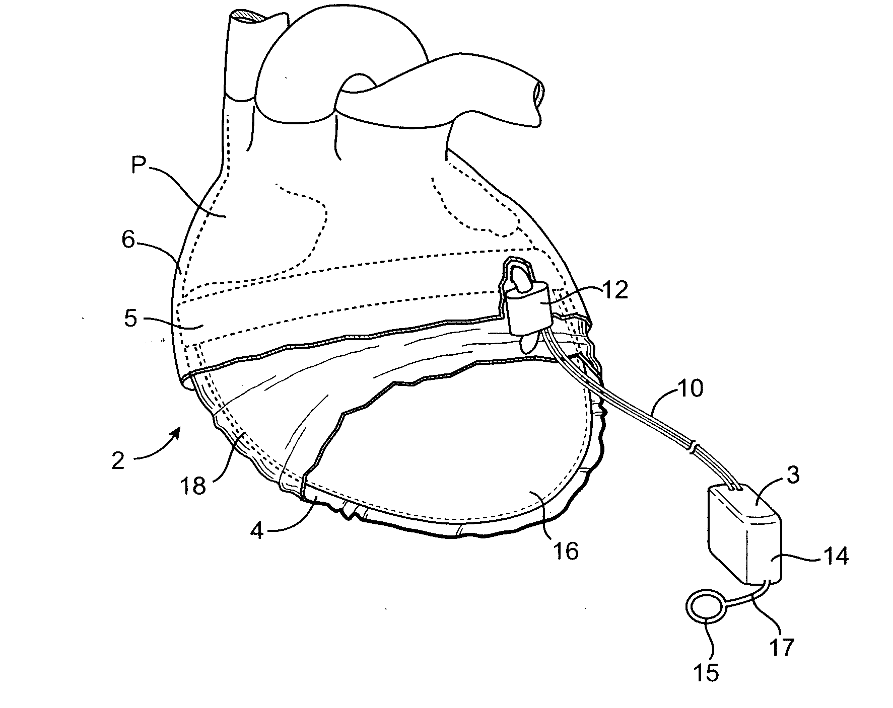
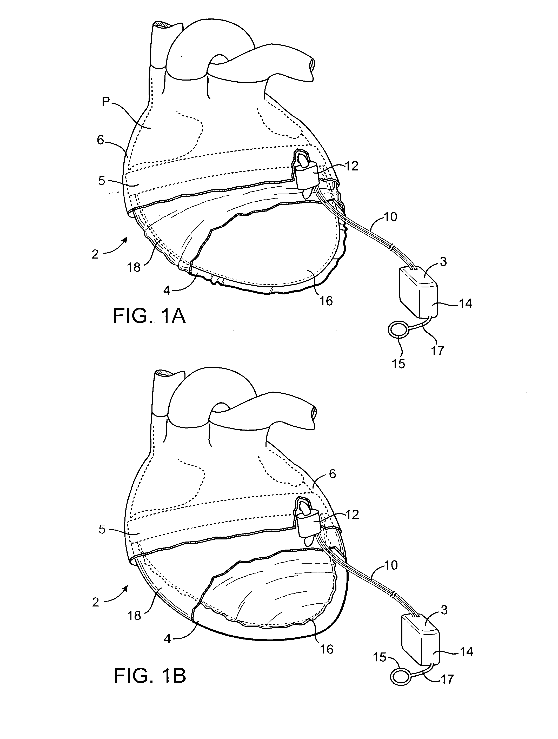
[0044] Referring to FIGS. 1-5, a cardiac assist device 2 in accordance with the present invention is shown. The device 2 includes a first pumping space 4 which assists one or both ventricles and a second pumping space 6 which assists one or both atria in pumping blood. Fluid (for example, a gas such as CO2 or a liquid such as saline) is pumped into and out of the pumping spaces 4, 6 so that fluid pressure is exerted on the outside wall of the heart to aid the heart in pumping blood. As will be discussed below, some advantages are found when practicing both atrial and ventricular support, however, the present invention provides aspects for atrial and ventricular support which may be practiced independently.

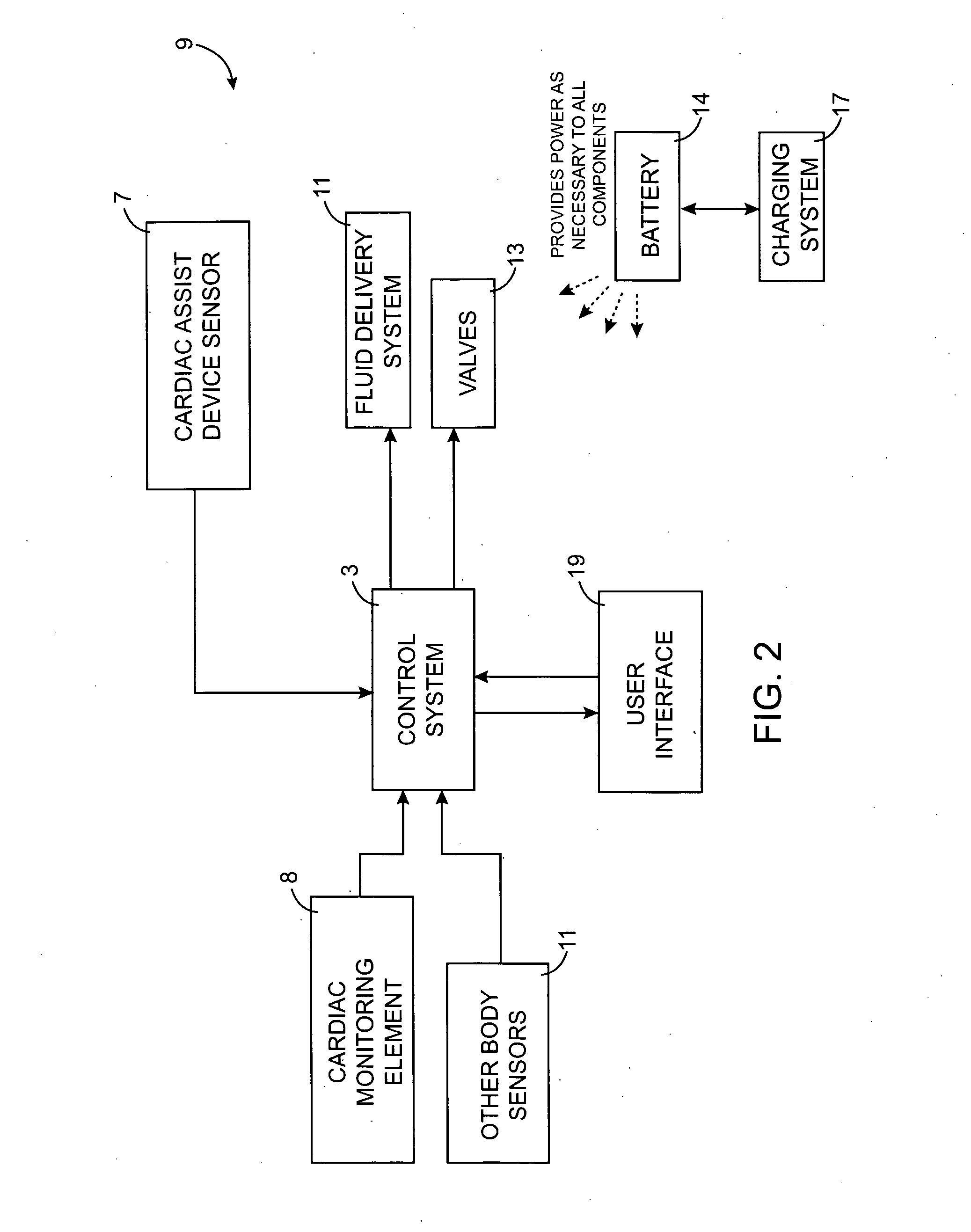
[0045] The cardiac assist device 2 includes a cardiac monitoring device 8 with one or more leads 10 attached to the heart to monitor cardiac activity. The cardiac monitoring device 8 is coupled to a pump 12 through a control system 3, which may be integrated with a battery 14, so ...


PUM


Abstract

The present invention provides a cardiac assist device which exerts pressure against the epicardial surface to assist the heart in pumping blood. The device may form a pumping space adjacent to an epicardial ventricular surface and/or an epicardial atrial surface. The cardiac assist device may permit the fluid to come into direct contact with the epicardium. The cardiac assist device may include a flexible jacket which at least partially collapses when fluid is withdrawn from the pumping space.

Description

RELATED APPLICATIONS [0001] This application claims the benefit of U.S. Provisional Application No. 60 / 678,957 filed May 6, 2005, which is hereby incorporated by reference.BACKGROUND OF THE INVENTION [0002] The present invention is related to devices and methods for assisting the heart. In particular, the present invention is related to devices and methods which apply external fluid pressure to the heart to assist the heart in pumping blood. The present invention may be used to assist the heart for any reasons but is particularly useful in treating congestive heart failure. Congestive heart failure is a common and often highly debilitating disease that progressively reduces the ability of the heart to pump blood. SUMMARY OF THE INVENTION [0003] The present invention provides various methods and devices for assisting the heart in pumping blood. The present invention provides methods and devices for assisting one or more atria and / or one or more ventricles which may be combined or pra...

Claims


Application Information

Patent Timeline
Patent Type & Authority Applications(United States)
IPC IPC(8): A61M1/10
CPCA61B2018/00351A61M1/106A61N1/3627A61M2230/04A61M1/1068A61M2205/8243A61M60/289A61M60/878A61M60/531A61M60/191A61M60/468A61M60/523A61M60/538A61M60/515A61M60/873A61M60/861
Inventor VASKA, MATTHIAS
Owner VASKA MATTHIAS
Why Eureka
Try Eureka