Balloon catheter having a flexible distal end

a balloon catheter and flexible technology, applied in balloon catheters, catheters, surgery, etc., to achieve the effects of improving handling and performance, excellent maneuverability and cross-ability, and decreasing flexibility

Inactive Publication Date: 2007-03-22
ABBOTT CARDIOVASCULAR
View PDF15 Cites 0 Cited by
  • Summary
  • Abstract
  • Description
  • Claims
  • Application Information

AI Technical Summary

Benefits of technology

[0009] In one embodiment, the distal skirt section of the balloon forms the wedge-shaped outer sheath around the distal end of the shaft. In an alternative embodiment, the outer sheath is a sleeve member having at least a portion located distal to the distal end of the balloon. The wedge-shaped distal end has an angled (i.e., truncated) end formed by a distal leading face which is oriented at an angle of about 30 to about 60 degrees, more preferably about 45 to about 55 degrees relative to the longitudinal axis of the shaft. The wedge-shaped end of the outer sheath provides distally increasing flexibility for a smooth transition in stiffness along the distal end of the catheter, to improve handling and performance and minimize kinking. In a presently preferred embodiment, the outer sheath has a proximal cylindrical section proximal to the wedge-shaped distal end. The proximal section of the outer sheath preferably has a circular or oblong transverse cross sectional shape, although it can have a variety of suitable shapes.
[0010] In a presently preferred embodiment, a distal tip member having at least a portion distal to the inner tubular member forms the distal end of the shaft, and defines a distal portion of the guidewire lumen in fluid communication with the portion of the guidewire lumen defined by the inner tubular member. The distal tip member provides improved flexibility at the shaft distal end for improved maneuverability. However, in an alternative embodiment, the distal tip member is omitted, and the distal end of the inner tubular member defines the distal end of the shaft. The distal tip member is typically softer and more flexible than the inner tubular member. In one embodiment, the distal tip member is formed of a material having a lower Shore Durometer hardness than a polymeric material forming at least part of the inner tubular member, to provide a soft, flexible, atraumatic distal end, which consequently provides improved catheter maneuverability and decreases the risk of damage to the patient's vessel during advancement of the catheter therein. The Shore Durometer hardness of the polymeric material forming the tip member is typically about 40D to about 70D, preferably about 55D to about 65D. In a presently preferred embodiment, the distal tip member is formed of a polyurethane, including a polyurethane copolymer such as PELLETHANE (a polyester polyurethane copolymer), available from Dow Plastics. However, the distal tip member may be formed of a variety of suitable materials, including polyolefin based copolymers such as a polyethylene based adhesive polymers such as an ethylene-acrylic acid copolymer which is sold commercially as PRIMACOR by Dow Chemical Co., and polyether block amide polymer such as PEBAX (available from Autochem).
[0013] The catheter of the invention has excellent maneuverability and crossability due to the distal end of the catheter having a wedge-shaped outer sheath around the distal end of the shaft. The wedge-shaped outer sheath provides gradually decreasing flexibility at the catheter distal end, for improved handling and performance. Moreover, in the embodiment having a soft distal tip forming the distal end of the shaft, the catheter has excellent tensile strength at the distal tip attachment, without

Problems solved by technology

One difficulty has been forming a connection between the soft tip and the catheter which is sufficiently strong to prevent disengagement of the soft tip or kinking at the junction between the soft tip and catheter shaft.

Method used


Image

  • Balloon catheter having a flexible distal end
  • Balloon catheter having a flexible distal end
  • Balloon catheter having a flexible distal end

Examples


Embodiment Construction

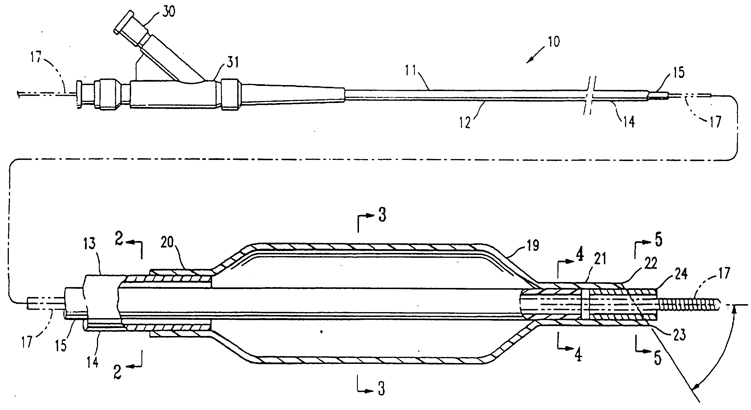
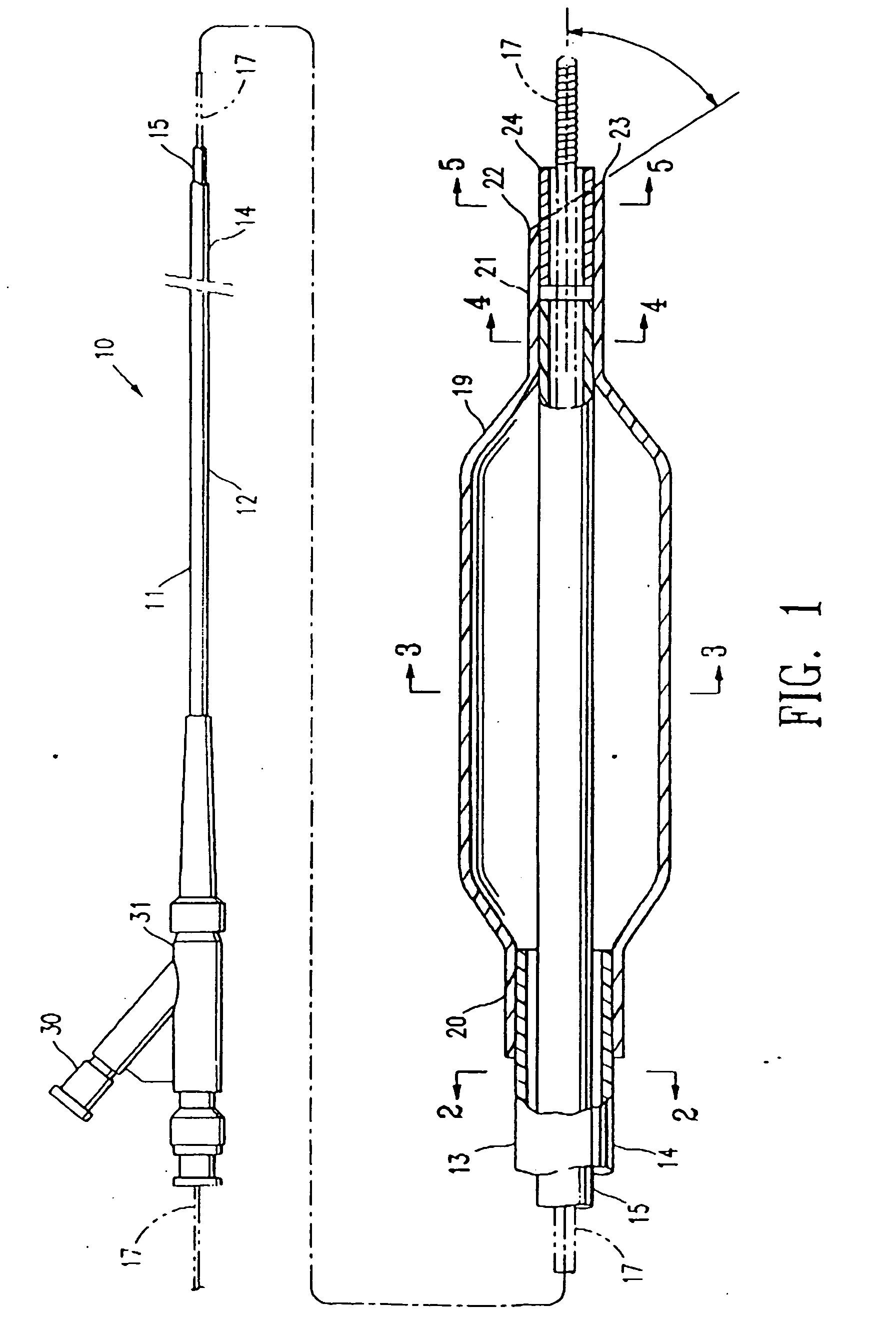
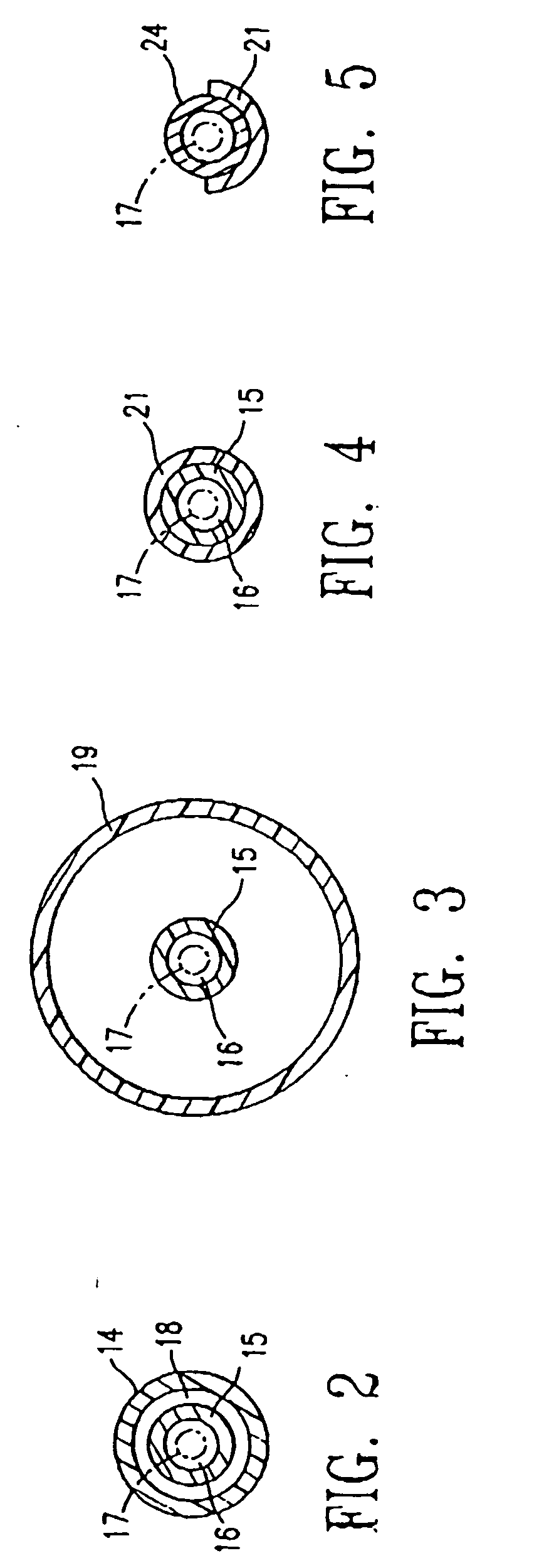
[0014]FIG. 1 illustrates an over-the-wire balloon catheter 10 embodying features of the invention. Catheter 10 generally comprises an elongated catheter shaft 11 having a proximal end, a distal end, a proximal shaft section 12, a distal shaft section 13, an outer tubular member 14, and an inner tubular member 15. Inner tubular member 15 defines a guidewire lumen 16 adapted to slidingly receive a guidewire 17, and the coaxial relationship between outer tubular member 14 and inner tubular member 15 defines annular inflation lumen 18, as best shown in FIG. 2, illustrating a transverse cross section of the catheter of FIG. 1, taken along line 2-2. An inflatable balloon 19 is disposed on the distal shaft section 13, having a proximal skirt section 20 sealingly secured to the distal end of outer tubular member 14, and a distal skirt section 21 sealingly secured to the distal end of inner tubular member 15, so that its interior is in fluid communication with inflation lumen 18. An adapter ...


PUM

PropertyMeasurementUnit
angleaaaaaaaaaa
angleaaaaaaaaaa
angleaaaaaaaaaa

Abstract

A catheter having an elongated shaft with a proximal end, a distal end, and at least one lumen, and a distal portion of the shaft being at least in part within an outer sheath having a wedge-shaped distal end. In one embodiment, the outer sheath around the distal end of the shaft is the distal skirt section of the balloon. In an alternative embodiment, the outer sheath is a sleeve member having at least a portion located distal to the distal end of the balloon.

Description

BACKGROUND OF THE INVENTION [0001] This invention generally relates to catheters, and particularly intravascular catheters for use in percutaneous transluminal coronary angioplasty (PTCA) or for the delivery of stents. [0002] In percutaneous transluminal coronary angioplasty (PTCA) procedures a guiding catheter is advanced in the patient's vasculature until the distal tip of the guiding catheter is seated in the ostium of a desired coronary artery. A guidewire is first advanced out of the distal end of the guiding catheter into the patient's coronary artery until the distal end of the guidewire crosses a lesion to be dilated. A dilatation catheter, having an inflatable balloon on the distal portion thereof, is advanced into the patient's coronary anatomy over the previously introduced guidewire until the balloon of the dilatation catheter is properly positioned across the lesion. Once properly positioned, the dilatation balloon is inflated with inflation fluid one or more times to a...

Claims


Application Information

Patent Timeline
Patent Type & Authority Applications(United States)
IPC IPC(8): A61M29/00A61F2/958A61M25/00
CPCA61M25/10A61M2025/1093A61M25/1034
Inventor DUCHAMP, JACKY G.GERVAIS, MISTY LYNNBAERGA, TERESITA
Owner ABBOTT CARDIOVASCULAR
Why Eureka
Try Eureka