
Suspension irregularity detecting system

a suspension system and irregularity detection technology, applied in underwater vessels, non-deflectable wheel steering, special data processing applications, etc., can solve the problems of increasing the difficulty of safely cornering and braking a vehicle, reducing the contact between the road surface tires, etc., to achieve the desired ride comfort and handling performance level, reduce the amount of tire contact, and detect the

Inactive Publication Date: 2007-03-22
FORD GLOBAL TECH LLC
View PDF14 Cites 28 Cited by
  • Summary
  • Abstract
  • Description
  • Claims
  • Application Information

AI Technical Summary

Benefits of technology

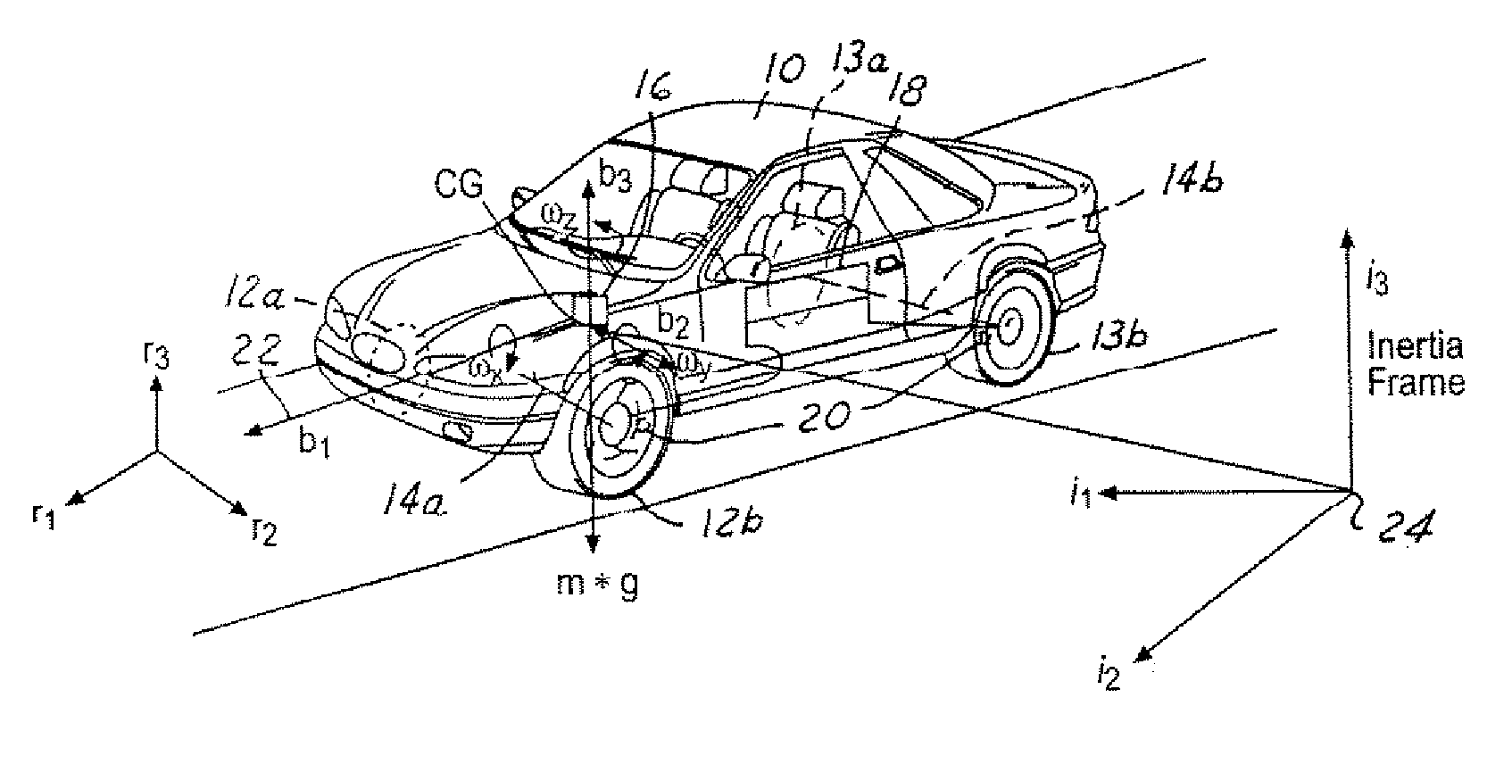
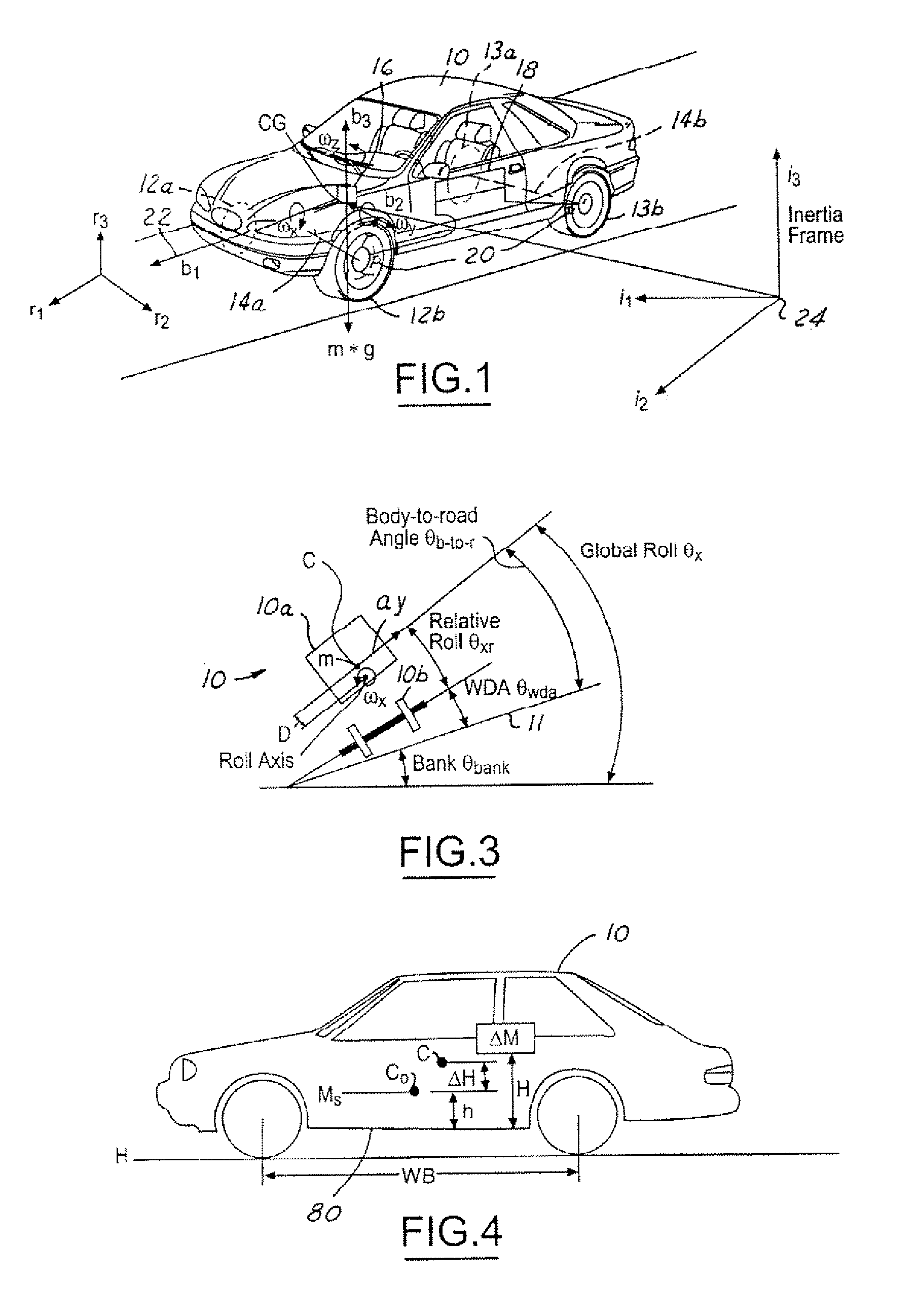
[0015] The embodiments of the present invention provide several advantages. One advantage provided by an embodiment of the present invention is the ability to detect suspension irregularities without use of additional hardware. Such detection and the information associated therewith is useful in adjusting vehicle characteristics, such as braking characteristics, steering characteristics, and suspension system characteristics to prevent and mitigate a vehicle roll situation. Such information is also useful to provide a warning signal to the driver of the vehicle indicating that one or more of the vehicle suspension components need to be repaired or replaced to restore a desired ride comfort and handling performance level. Maintaining a vehicle with a desired damping level allows for operation safety maintenance of a vehicle. When suspension dampers are degraded or have an irregularity excessive vehicle roll and pitch motions and weight transfers can occur, which further reduces the amount of tire contact with a road surface. Reduced road surface tire contact increases difficulty in safely cornering and braking a vehicle.
[0016] The present invention also uses the suspension irregularity information to adjust the vehicle chassis controls to improve the performance of vehicle active systems.

Problems solved by technology

Reduced road surface tire contact increases difficulty in safely cornering and braking a vehicle.

Method used


Image

  • Suspension irregularity detecting system
  • Suspension irregularity detecting system
  • Suspension irregularity detecting system

Examples


Embodiment Construction

[0029] A vehicle suspension system is designed to support weight, absorbs and dampens shock and vibration of the vehicle body and the wheels, and helps maintain a good contact between the tire and the road surface. A vehicle suspension system consists of three components: springs, dampers, and anti-sway bars.

[0030] The suspension springs in the suspension system hold up the weight of the vehicle and help the vehicle body to resist the so-called pitch motion (front-to-rear angular motion) and roll motion (side-to-side angular motion) thereof. The suspension springs may be in the form of coil springs, leaf springs, or air springs and include torsion bars. The physical characterization of the suspension springs is their stiffness, which is the force per unit displacement of the suspenion height, that affects how the vehicle body responds while the vehicle is being driven on a road. For low stiffness springs, such as those used in luxury cars, the vehicle body does not easily respond t...


PUM


Abstract

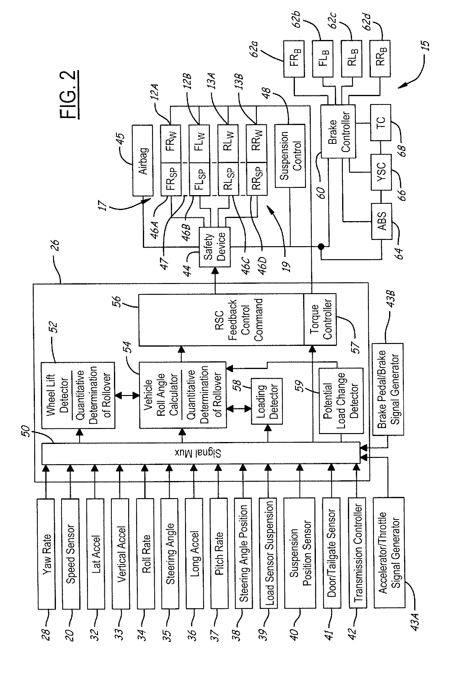
A vehicle suspension system (19) includes a suspension (47). A lateral acceleration sensor (32) generates a lateral acceleration signal. A roll rate sensor (34) generates a roll rate signal. A controller (26) detects an irregularity in the suspension in response to the lateral acceleration signal and the roll rate signal. A method of detecting suspension irregularities in a vehicle (10) includes the generating of a lateral acceleration signal and a roll rate signal. Roll angle is determined in response to the lateral acceleration signal and roll rate signal. A roll gradient, a roll acceleration coefficient, and a roll damping parameter are determined in response to at least the roll angle. The roll gradient, the roll acceleration coefficient, and the roll damping parameter are compared to associated nominal values. A suspension irregularity is indicated in response to the comparison.

Description

RELATED APPLICATION [0001] The present application is a continuation-in-part of U.S. patent application (Attorney Docket 81103817 (FGT 1935 PA) Ser. No. 10 / 972,973 filed on Oct. 25, 2004, which is a continuation-in-part of U.S. patent application (Attorney Docket 81044320 (FGT 1893 PA)) Ser. No. 10 / 966,395 filed on Oct. 15, 2004. The disclosures of the stated applications are incorporated by reference herein.TECHNICAL FIELD [0002] The present invention relates generally to vehicle control systems, vehicle sensing systems, and suspension systems. More particularly, the present invention is related to techniques for detecting suspension system irregularities and responding thereto. BACKGROUND [0003] Recently, vehicle roll stability control (RSC) schemes, i.e., U.S. Pat. No. 6,324,446, have been proposed to address the issue of friction-induced rollovers. RSC system includes a variety of sensors sensing vehicle states and a controller that controls a distributed brake pressure to reduc...

Claims


Application Information

Patent Timeline
Patent Type & Authority Applications(United States)
IPC IPC(8): B60G17/018B62D6/00B60T8/24B60R21/0132B60W10/18B60W10/20B60W10/22
CPCB60R21/0132B60T8/172B60T2230/03B60T2240/06B60W40/114B60W10/20B60W10/22B60W40/11B60W40/112B60W10/18B60G17/015B60T8/1755B60G2800/94B60G2800/9122B60G2800/92B60G2800/9124B60G2800/012B60T1/00
Inventor MESSIH, DAVIDLU, JIANBOSALIB, ALBERTCHUBB, ERIK
Owner FORD GLOBAL TECH LLC
Learn More