
Sensor network system, sensor node, sensor information collector, method of observing event, and program thereof

a sensor network and sensor information technology, applied in the field of sensor network systems, can solve problems such as the inability to enhance the precision (resolution) of information, and achieve the effect of suppressing congestion and high precision

Active Publication Date: 2007-03-22
NEC CORP
View PDF5 Cites 21 Cited by
  • Summary
  • Abstract
  • Description
  • Claims
  • Application Information

AI Technical Summary

Benefits of technology

[0050] The sensor node program in accordance with the present invention, which is a sensor node program that is installed in a computer, is characterized in causing the computer to perform a process of more preferentially transmitting the sensor information indicating the event detected by the sensor that exerts a larger influence upon a sensor information distribution indicating a temporal distribution or a spatial distribution of the event.
[0052] As explained above, the present invention makes it possible to suppress the congestion due to the sensor information transmitted by the sensor node, and to provide the application apparatus information having a high precision because the communicating means of the sensor node transmits the sensor information at a timing responding to an influence that the event detected by the sensor exerts upon the sensor information distribution.

Problems solved by technology

However, like the case of the apparatus described in the patent document 1, shortening the period at which the sensor node transmits information in some cases, or increasing the spatial arrangement density of the sensor node in order to enhance the spatial resolution of information that the sensor node transmits in some cases incur occurrence of the response implosion problem that all of the sensor nodes having observed the identical event transmit a large quantity of data all at once.
The reason is that, in the prior art, it is impossible to enhance the precision (resolution) of information, which the sensor node transmits, without increasing the traffic quantity.

Method used


Image

  • Sensor network system, sensor node, sensor information collector, method of observing event, and program thereof
  • Sensor network system, sensor node, sensor information collector, method of observing event, and program thereof
  • Sensor network system, sensor node, sensor information collector, method of observing event, and program thereof

Examples


embodiment 1

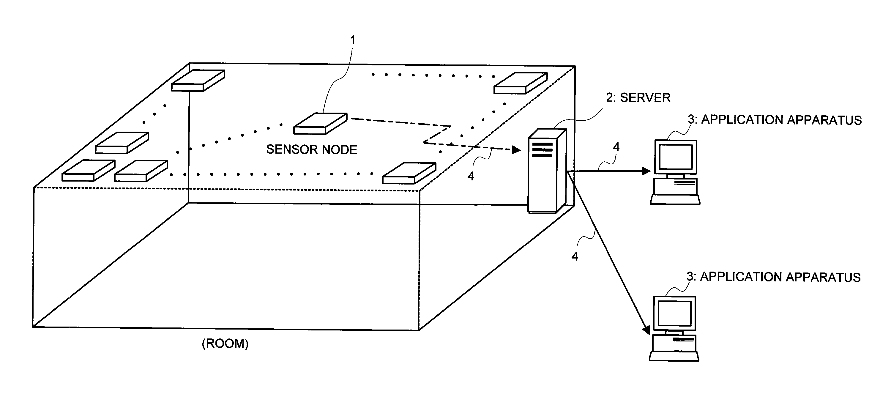
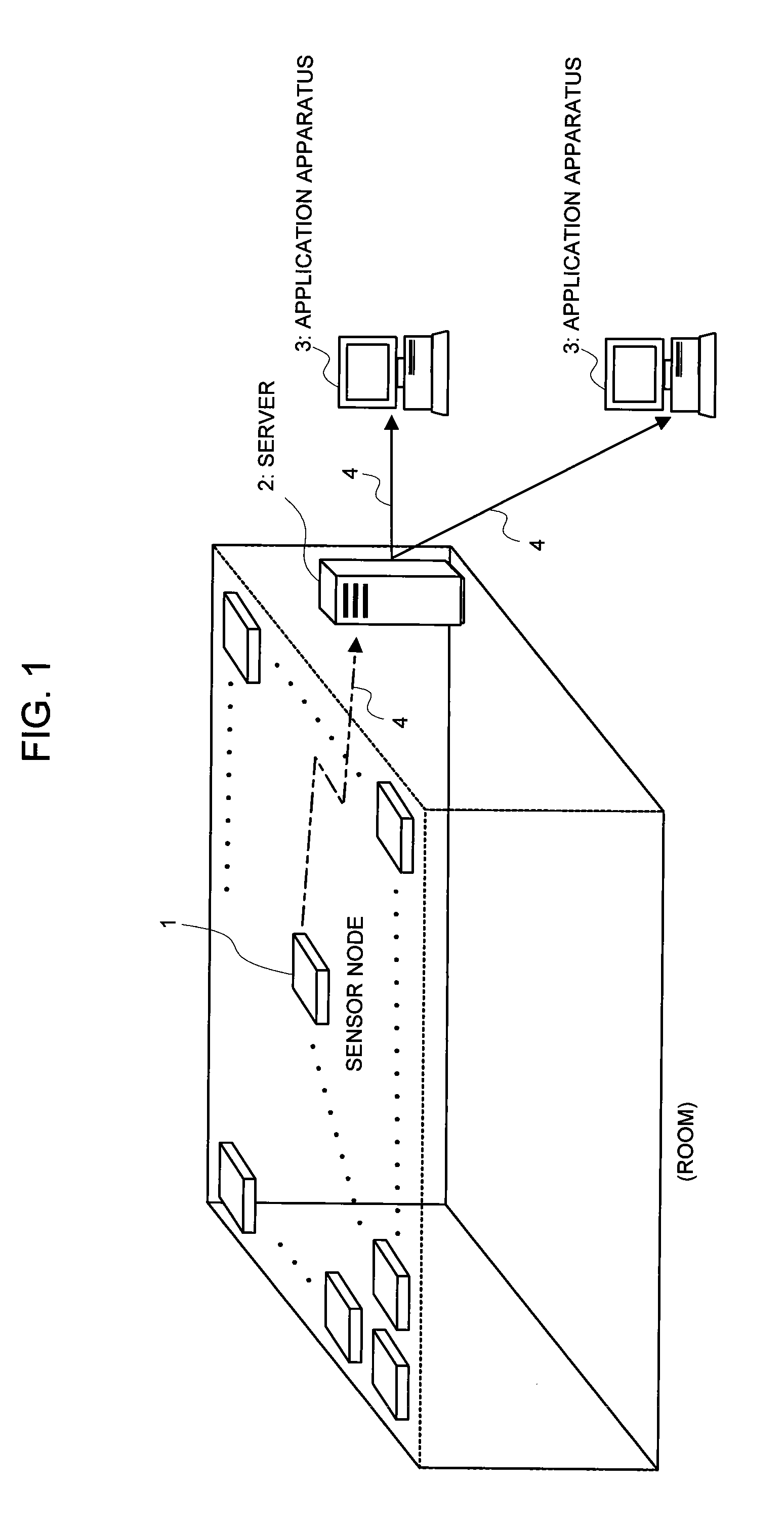
[0076] A first embodiment of the present invention will be explained by making a reference to the accompanied drawings. FIG. 1 is an explanatory view illustrating one configuration example of the sensor network system in accordance with the present invention.

[0077] The first embodiment of the sensor network system in accordance with the present invention includes a plurality of sensor nodes 1 for detecting the event to transmit sensor information, being information indicating the detected event, which are installed into a room etc., a server 2 for receiving the sensor information transmitted by the sensor node 1, an application apparatus 3 for utilizing the sensor information, and a communication network 4 for connecting the sensor node 1, the server (sensor information collector) 2, and the application apparatus 3.

[0078] The sensor node 1 transmits the sensor information to the server 2 via the communication network 4. The sensor node 1, which, for example, is small-sized, has le...

embodiment 2

[0113] Next, a second embodiment of the present invention will be explained by making a reference to the accompanied drawings. FIG. 4 is a block diagram illustrating one configuration example of the second embodiment of the present invention.

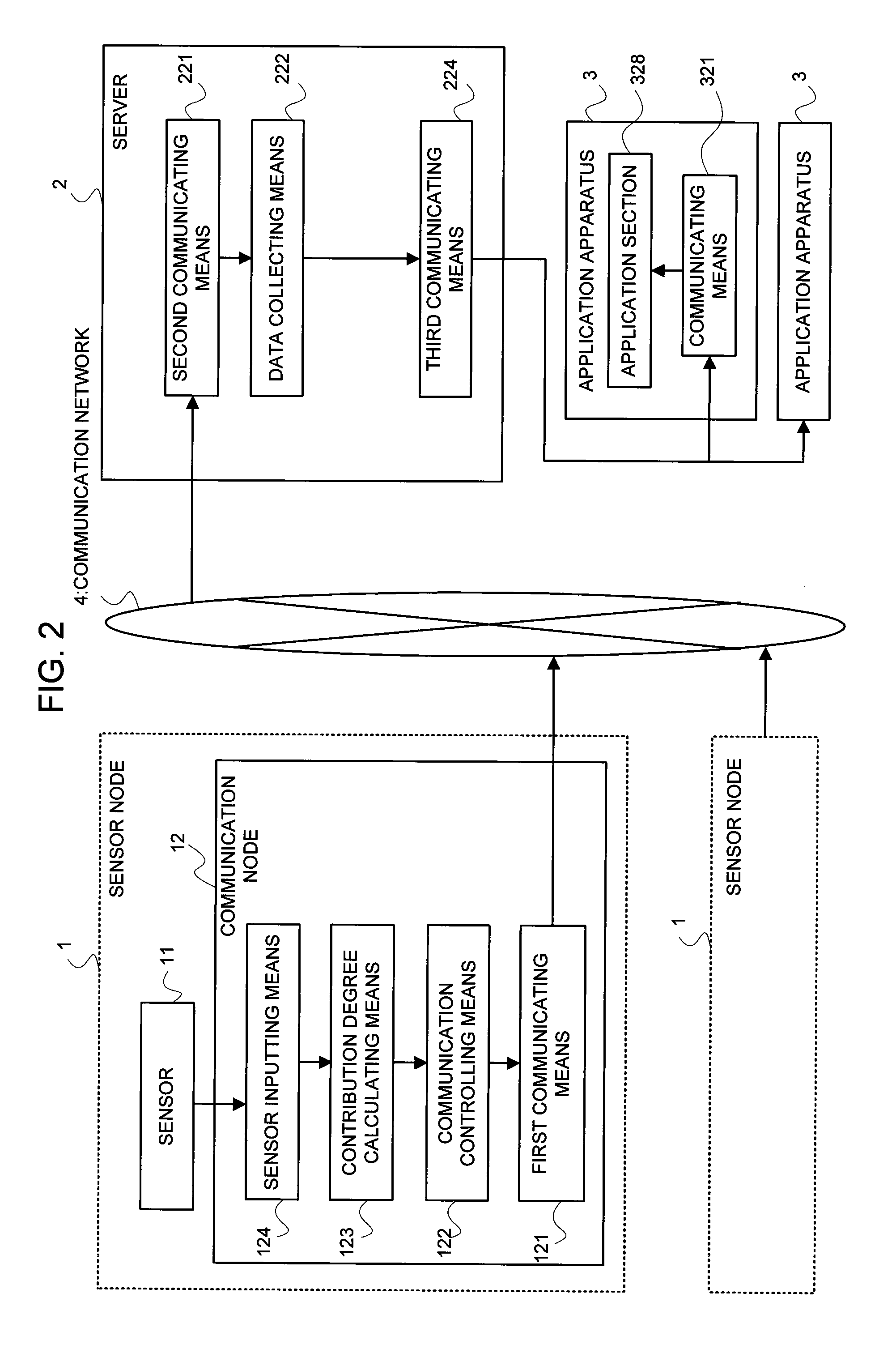
[0114] The configuration of the second embodiment of the present invention differs from that of the first embodiment shown in FIG. 2 in a point that the former does not include the server 2, but includes a plurality of application apparatuses (sensor information collectors) 3 each having a second communicating means 221 for receiving the sensor information from the sensor node 1, a data collecting means 222, and an application section 328. The configuration other than this is similar to that of the first embodiment, so the identical code to that of FIG. 2 is affixed hereto, and explanation is omitted.

[0115] In this embodiment, the sensor node 1 does not make many-to-one communication with the server 2, but makes many-to-many communication with...

embodiment 3

[0120] Next, a third embodiment of the present invention will be explained by making a reference to the accompanied drawings. FIG. 5 is a block diagram illustrating one configuration example of the third embodiment of the present invention.

[0121] The configuration of this embodiment differs from that of the first embodiment shown in FIG. 2 in a point that the server 2 has an estimating means 223. The configuration other than this is similar to that of the first embodiment, so the identical code to that of FIG. 2 is affixed hereto, and explanation is omitted.

[0122] The estimating means 223 forecasts / estimates / complements the sensor information that is deficient, estimates the latest sensor information, thereby to restore the sensor information distribution based upon the event model, from the information (including the contribution degree, the communication control information, and the additional information such as the term of validity) associated with the sensor except the sensor...


PUM


Abstract

In a sensor network system, sensor data having a high precision (high resolution) is collected, and yet congestion of a communication network and an apparatus for processing the sensor data is suppressed. A sensor node 1 has a contribution degree calculating means 123 for calculating an influence that the detected sensor information exerts upon the entire precision (resolution). And, a first communicating means 121 transmits sensor information responding to a calculated contribution so that no congestion caused by transmitting a large quantity of data all at once occurs.

Description

BACKGROUND OF THE INVENTION [0001] The present invention relates to a sensor network system, a sensor node, a sensor information collector, a method of observing an event, and a program thereof, and more particularly to a sensor network system having a sensor information collection function with a high precision (high resolution) and a congestion suppression function, a sensor node, a sensor information collector, a method of observing an event, and a program thereof. [0002] As a means for collecting information detected by a plurality of sensors installed in a room, a building, etc. there exists a sensor network. The sensor network includes a sensor node that detects and transmits the event. [0003] And, so as to enhance a precision (resolution) of the information detected by the sensor, there exist the apparatus for shortening a period at which the sensor node transmits information, thereby to enhance a temporal resolution (see, for example, patent document 1) and the method of enh...

Claims


Application Information

Patent Timeline
Patent Type & Authority Applications(United States)
IPC IPC(8): G06F3/00
CPCH04L12/2602H04L43/00H04L43/0882H04L45/00G01D21/00H04L47/11G01D1/00G01K3/10G01K3/14H04L47/10G01K1/026G01K7/42G01K2213/00
Inventor TAKAOKA, MASANORINAKAO, TOSHIYASU
Owner NEC CORP
Learn More