
Tapered toroidal flow control valve and fuel metering device

Inactive Publication Date: 2007-03-29
WRIGHT GORDON FRASER
View PDF4 Cites 27 Cited by
  • Summary
  • Abstract
  • Description
  • Claims
  • Application Information

AI Technical Summary

Benefits of technology

[0014] Ease of position measurement and use of smaller and less expensive actuators. It is possible to use reliable and less expensive guide bearings. The proportional solenoid required by an equivalent stroke linear motion valve would be larger, heavier and more expensive than the rotary actuator.
[0015] The device of the invention can seal the gas passage.
[0016] The tapered toroidal valve is geometrically similar to a conical valve, the profile of which can be advantageously shaped to mee

Problems solved by technology

There are several major shortcomings associated with the aforementioned technologies, the most serious of which are the airflow restriction created by the venturi and the closed loop control problems.
Due to the complexity of the flow phenomena through the venturi, carburetors are difficult to integrate into control systems.
The drawbacks of the butterfly valve solution are the impossibility to seal fuel flow completely, a usable angular stroke lesser than 90 degrees and the difficulty in profiling the valve to match fuel flow requirements.
There are, however, at least two main problems with the linear type actuator required to drive such a valve: in order to increase control resolution, it is desirable to extend the cone profile as much as possible.
This entails a long actuator stroke, which leads to large, heavy and expensive actuators.
The other problem is the difficult and expensive means to measure the linear position of the conical valve.

Method used


Image

  • Tapered toroidal flow control valve and fuel metering device
  • Tapered toroidal flow control valve and fuel metering device
  • Tapered toroidal flow control valve and fuel metering device

Examples


Embodiment Construction

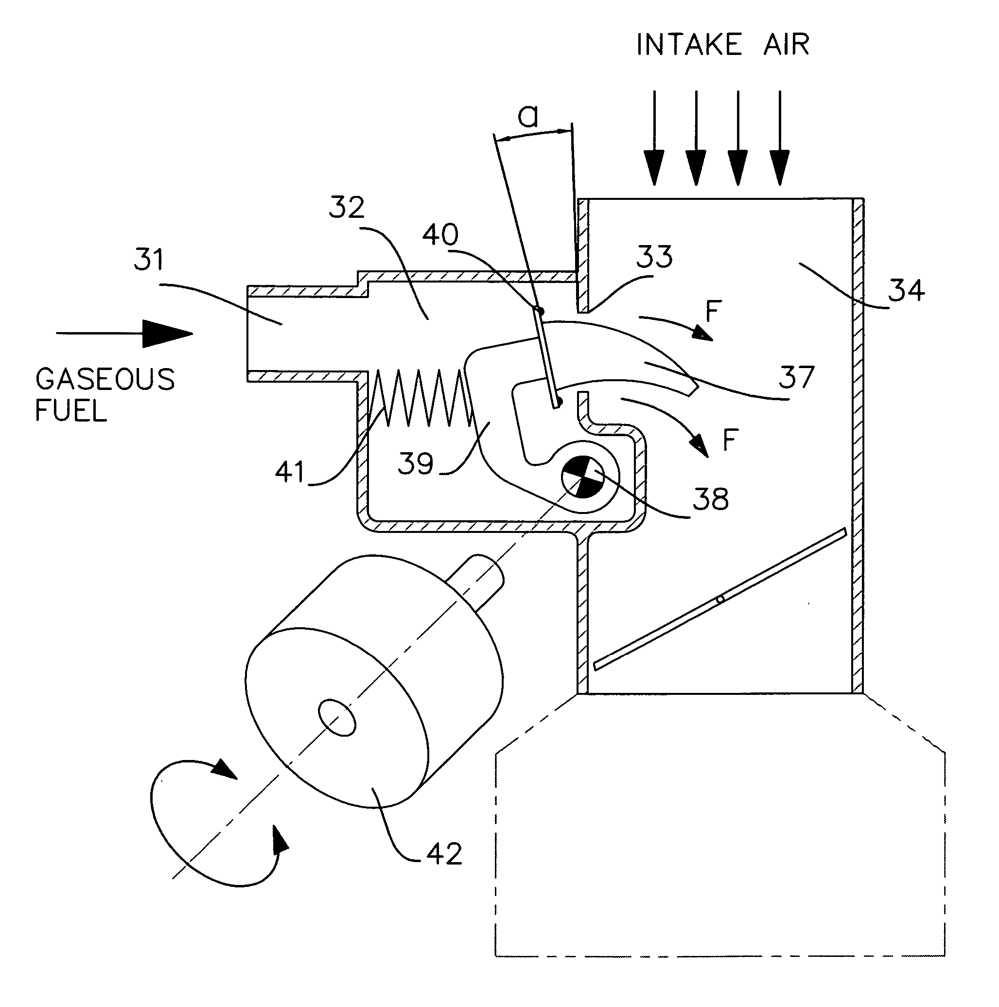
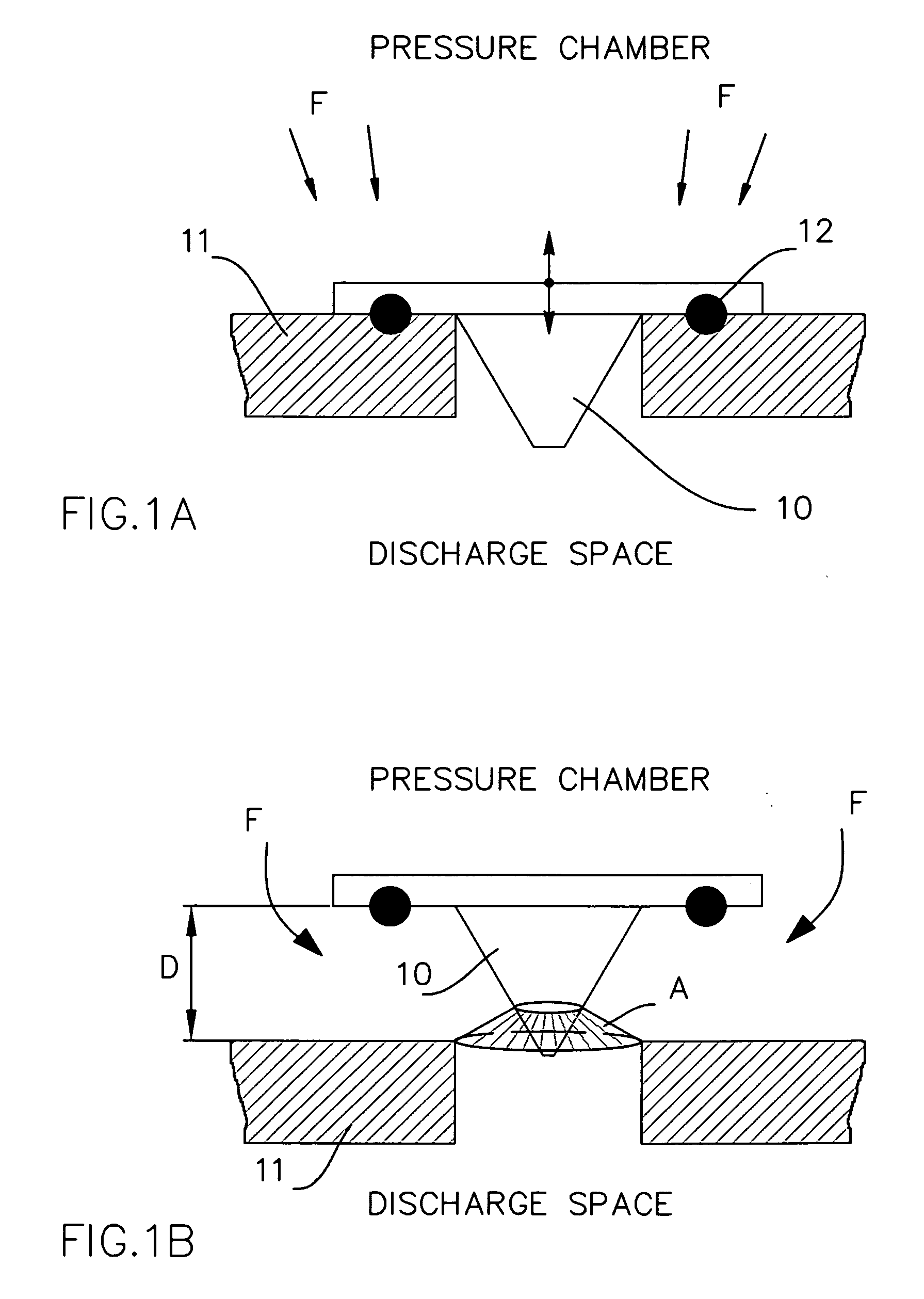
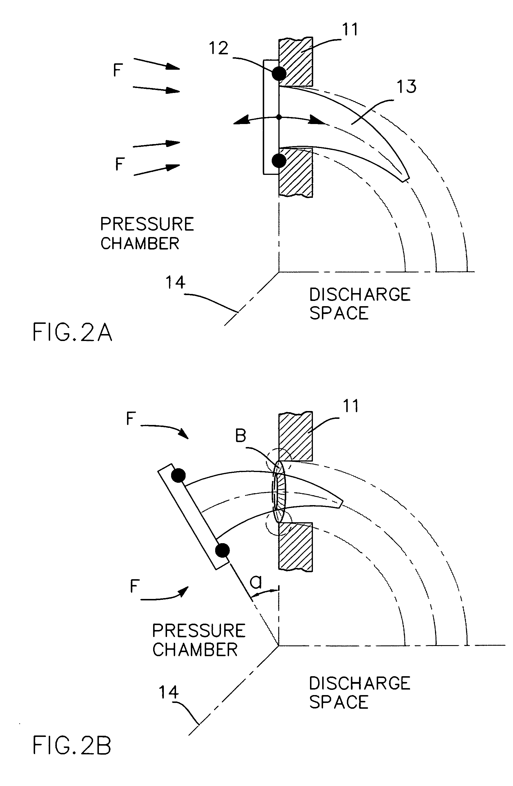
[0062]FIGS. 1 and 2 refer to the fluid flow control valve geometry, compared to a linear travel conical valve. FIG. 3 relates to the fuel metering device of the invention. FIGS. 4 and 5 capture additional features of the flow control valve. FIG. 6 shows another embodiment of the metering device.

[0063]FIG. 1A and FIG. 1B review the operating principle of a linear travel conical valve. FIG. 1A shows a conical valve, 10, in its closed position against a seat 11. In the closed position, a seal 12 provides a fluid tight seal between a pressure chamber and a discharge space. The pressure chamber contains a fluid F, under a pressure substantially higher than the pressure in the discharge space.

[0064] Referring now to FIG. 1B, conical valve 10 is shown in a lifted position, at a distance D from the seat, thereby opening a flow area A for fluid F to flow through. Conical valve 10 now meters the flow of the fluid, from the pressure chamber into the discharge space. It is apparent that flow ...


PUM


Abstract

A novel flow control valve for metering a fluid flow between a pressure chamber and a discharge space, and a fuel metering device utilizing this flow control valve are disclosed. The flow control valve is a tapered toroid, rotating about a fixed axis. A seal means, fixedly mounted to the valve, fluidically isolates the pressure chamber from the discharge space when the valve is in its closed position. The fuel metering device utilizes said tapered toroidal flow control valve to deliver a precisely metered amount of a preferably gaseous fuel to an internal combustion engine. The fuel metering device comprises a rotary actuator capable to move the toroidal valve about a fixed fulcrum. Means, including springs, are provided to close the valve when the rotary actuator is de-energized. The device further comprises a rotary position sensor, which, in co-operation with said rotary actuator enable accurate angular positioning of the valve.

Description

[0001] This application claims benefit under 37 CFR 119e to provisional application 60 / 720313—Tapered Toroidal Flow Control Valve And Fuel Metering Device—filed on Sep. 23, 2005 by Gordon F Wright.CROSS-REFERENCE TO RELATED APPLICATIONS [0002] Not Applicable. STATEMENT REGARDING FEDERALLY SPONSORED RESEARCH OR DEVELOPMENT [0003] Not Applicable. REFERENCE TO MICROFICHE APPENDIX [0004] Not Applicable. BACKGROUND OF THE INVENTION [0005] This invention relates to fluid flow control systems and more particularly to gaseous fuels systems for internal combustion engines. [0006] With ever more stringent emissions regulations, the use of alternative gaseous fuels for operating internal combustion engines has become increasingly attractive. The more commonly used gaseous fuels are compressed natural gas (CNG) and liquefied petroleum gas (LPG). These gases can burn cleaner than gasoline and the cost per unit of energy is lower. [0007] Currently, the gaseous fuels industry still relies heavily ...

Claims


Application Information

Patent Timeline
IPC IPC(8): F02B43/00
CPCY02T10/32F02M21/0239F02M21/0233F02D19/027F02M21/04Y02T10/30
Inventor WRIGHT, GORDON FRASER
Owner WRIGHT GORDON FRASER
Learn More