Control device for synchronous motor

a control device and synchronous motor technology, applied in the direction of motor/generator/converter stopper, electronic commutator, dynamo-electric converter control, etc., can solve the problem of complex control, low speed, and inability to accurately estima

Inactive Publication Date: 2007-03-29
YASKAWA DENKI KK
View PDF6 Cites 27 Cited by
  • Summary
  • Abstract
  • Description
  • Claims
  • Application Information

AI Technical Summary

Benefits of technology

[0004] Therefore, it is an object of the invention to provide a control device for a synchronous motor which can cause the carrier signal of a PWM inverter to have an arbitrary phase difference between two of three phases of U, V and W. thereby generating a high frequency voltage and a high frequency current other than a driving frequency so that estimating the position of a magnetic pole can be carried out based on a relationship between the voltage and the current by the simplified control device without requiring a signal generator, and furthermore, this control device can also carry out a control from a zero speed.

Problems solved by technology

In the conventional art, however, an operation can be carried out with sufficient precision in a high speed area in a method of estimating the speed and position of a rotor based on the induced voltage of the motor, however, an accurate estimation cannot be carried out at a very low speed where less information is provided about an induced voltage.
However, there is a problem in that an additional signal generator is required for injecting the sensing signal and its control is also complicated.

Method used


Image

  • Control device for synchronous motor
  • Control device for synchronous motor
  • Control device for synchronous motor

Examples


Embodiment Construction

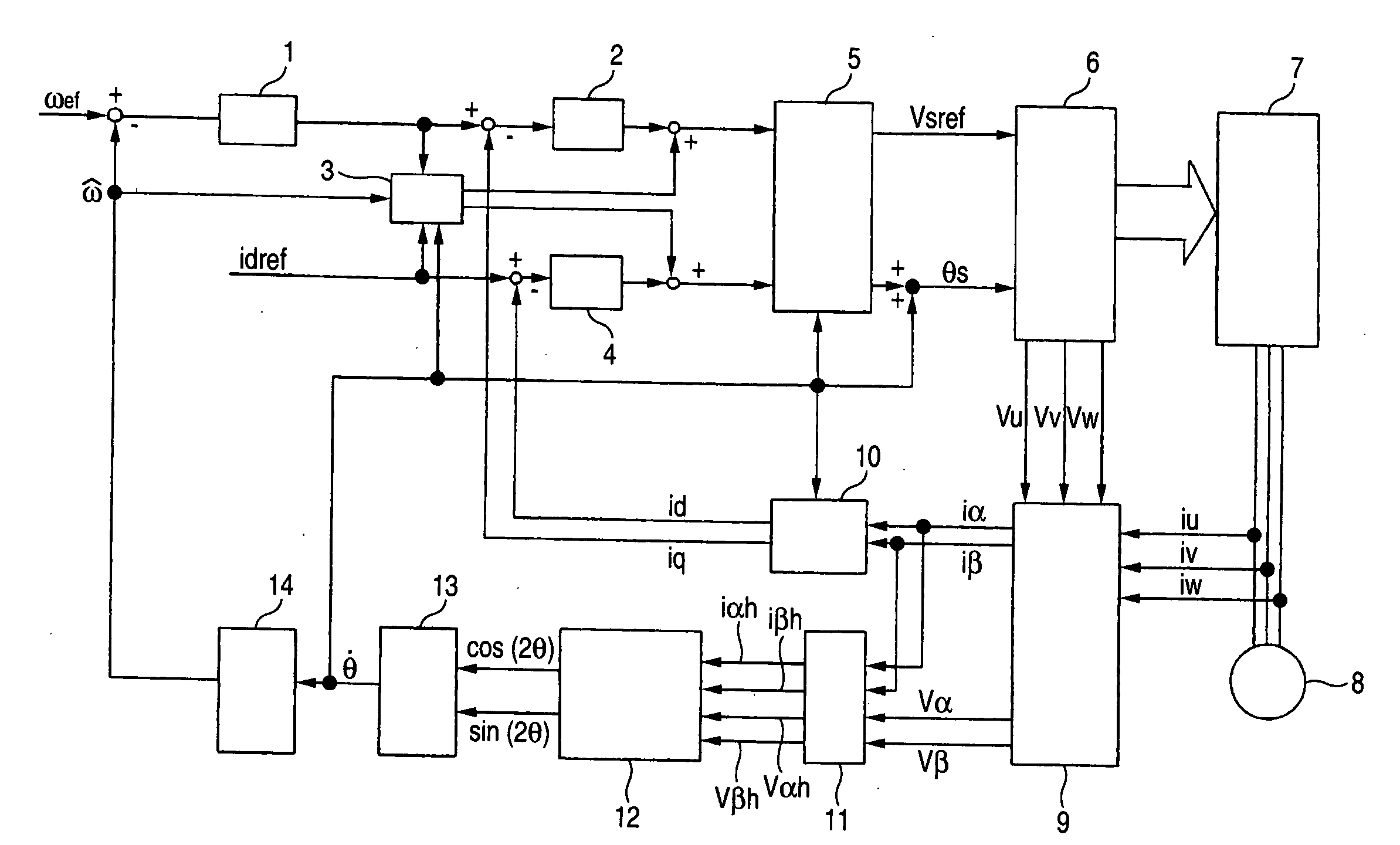
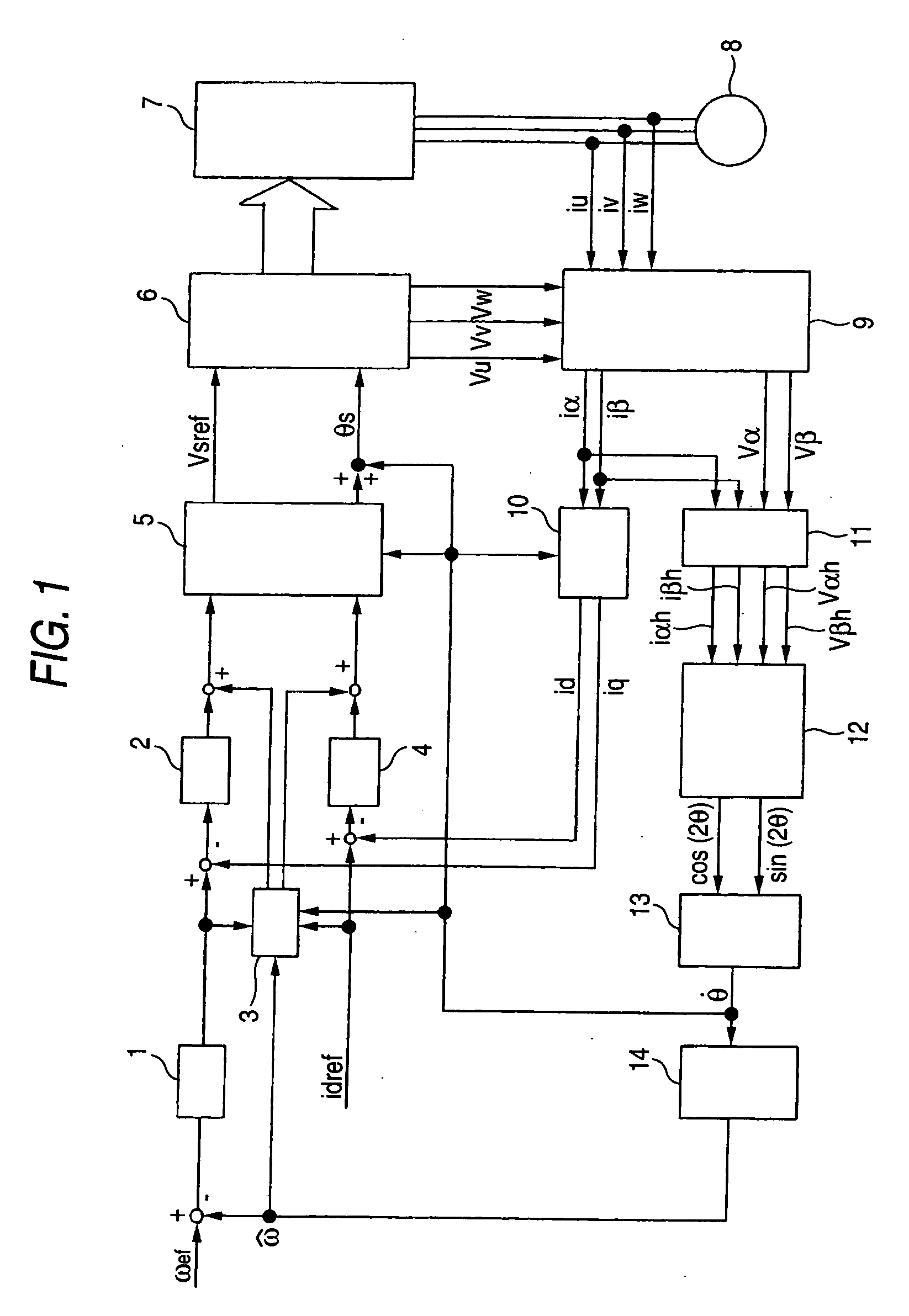
[0029] According to a control device for a synchronous motor, the invention is based on a method of detecting the position of a magnetic pole by using a current having a carrier frequency component in principle, and a control device having a current controller, a speed estimator and a speed controller is constituted by the system.

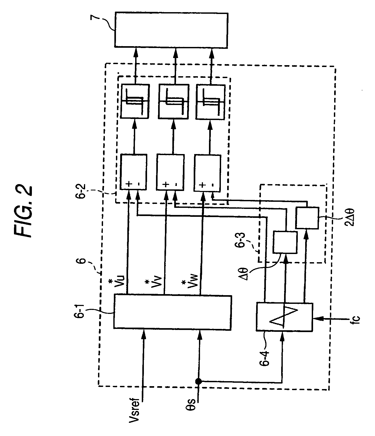
[0030] First of all, description will be given to the basic principle of the detection of the position of a magnetic pole. In a vector control device for a synchronous motor to be driven by a voltage-operated PWM inverter, a PWM carrier signal is caused to have an arbitrary phase difference between two phases such as UW, VW or WU in three phases of U, V and W, thereby generating a high frequency voltage and a high frequency current which are different from a driving frequency. More specifically, it is possible to regulate the frequency band of a generated high frequency component to have a different frequency from the driving frequency by arbitrarily givin...


PUM


Abstract

It is an object of the invention to provide a control device for a synchronous motor which can detect the position of a magnetic pole from a zero speed without requiring a signal generator.
The invention provides a control device for a synchronous motor which drives the synchronous motor through a voltage-operated PWM inverter and controls a torque and a speed of the motor, including means (6-3) for causing a PWM carrier signal to have an arbitrary phase difference between two phases such as UW, VW or WU in three phases of U, V and W, means (11) for extracting a high frequency voltage and a high frequency current which are thus generated from a detecting voltage or a command voltage and a detecting current, and means (12) for estimating a position of a magnetic flux or a position of a magnetic pole by using the high frequency voltage and the high frequency current which are extracted.

Description

TECHNICAL FIELD [0001] The present invention relates to a control device for an electric motor which serves to estimate the positions of a magnetic poles from a very low speed, including a zero speed, with high precision so as to control a torque and a speed based on the position of the magnetic pole thus estimated. BACKGROUND ART [0002] For a conventional magnetic pole estimating method, there has widely been used a method of calculating an induced voltage which is proportional to the speed of an electric motor based on an input voltage and a current of the electric motor and estimating a speed as reported in IEEE Paper D,. Vol. 108, No. 12, 1988 “Method of Controlling Adaptive Current of Brushless DC motor having Parameter Identifying Function”. Moreover, there has been proposed 1996 IEEE Industry Applications Society National Convention No. 170 “Zero Speed Torque Control of Salient-Pole Type Synchronous Motor using Sensorless System”. According to this system, an AC signal is sup...

Claims


Application Information

Patent Timeline
Patent Type & Authority Applications(United States)
IPC IPC(8): H02P1/46H02P6/18H02P6/06H02P6/08H02P6/182H02P21/00H02P21/14H02P21/22H02P23/14H02P25/022H02P27/04
CPCH02P21/0042H02P21/141H02P6/183H02P2203/11H02P2207/05H02P21/146H02P21/18H02P21/26
Inventor IDE, KOZOSAWAMURA, MITSUJIROSAWA, TOSHIHIROOYAMA, JUN
Owner YASKAWA DENKI KK
Why Eureka
Try Eureka