Surface light source device

a light source and surface technology, applied in the field of surface light source devices, can solve the problems of increasing the light loss in the interior of the optical waveguide, the more remarkable the luminance unevenness, and the more uneven luminance, so as to minimize the uneven luminance, and reduce the number of point sources

Active Publication Date: 2007-03-29
JVC KENWOOD CORP A CORP OF JAPAN
View PDF9 Cites 24 Cited by
  • Summary
  • Abstract
  • Description
  • Claims
  • Application Information

AI Technical Summary

Benefits of technology

[0016] Under the above-mentioned issues, an object of the present invention is to provide a surface light source device in which a plurality of point sources are lined up and which is used for a non-emission display device or the like. In such an objective surface light source device, in detail, even if reducing the number of point sources and a thickness of a light mixing chamber, luminance (brightness) in illumin...

Problems solved by technology

In the above-mentioned surface light source devices each having a plurality of point sources (light emission diodes) as the light source juxtaposed, however, the illumination light radiated from the exit surface of the optical waveguide is easy to cause luminance unevenness in connection with positioning of the point sources.
The longer a distance between one point source and its adjoining point source gets, the more remarkable the luminance unevenness becomes.
Additionally, if the optical waveguide having a sufficient thickness is...

Method used


Image

  • Surface light source device
  • Surface light source device
  • Surface light source device

Examples


first embodiment

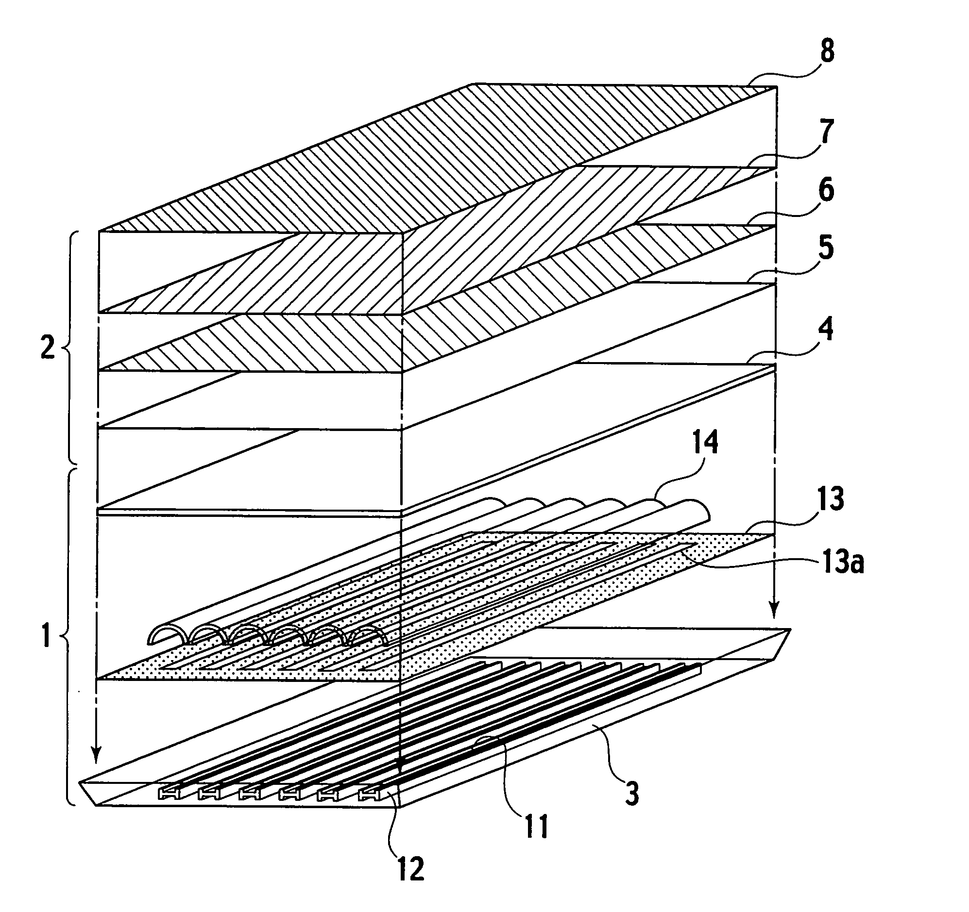
[0031]FIG. 1 is an exploded perspective view showing a constitution of a non-emission display device on which a surface light source device in accordance with the present invention is applied.

[0032] The surface light source device of the invention is used as an illuminating device in the non-emission display device, as shown in FIG. 1. This non-emission display device comprises a surface light source device 1 and a non-emission display part 2 forming an illuminated object illuminated by the surface light source device 1. Note that in FIG. 1, its upper side is defined as an exit side (front surface) of the surface light source device 1, while the lower side is defined as a rear side of the surface light source device 1.

[0033] The surface light source device 1 includes a light mixing chamber in the form of a casing, which accommodates a plurality of light emission diodes 11 forming a plurality of point sources and mixes respective colored lights emitted from the light emission diodes...

second embodiment

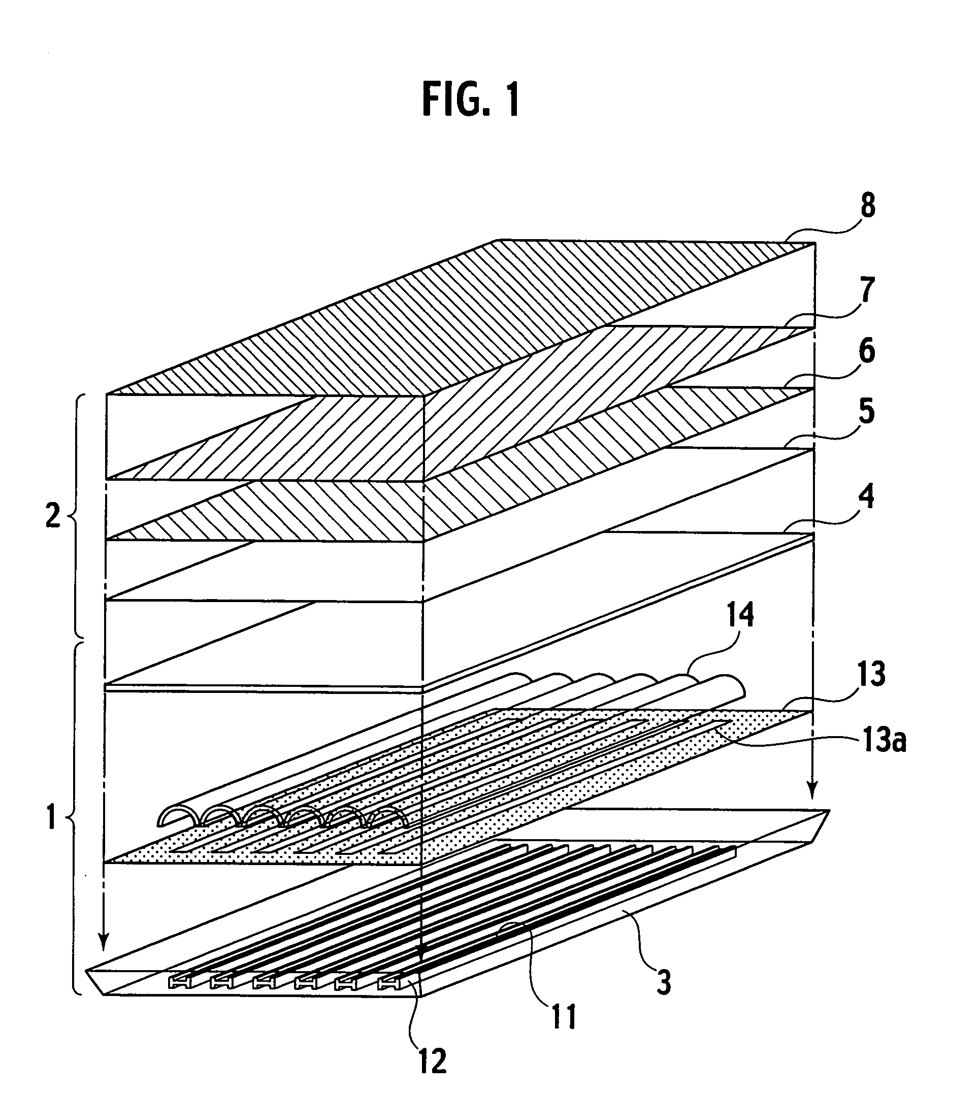
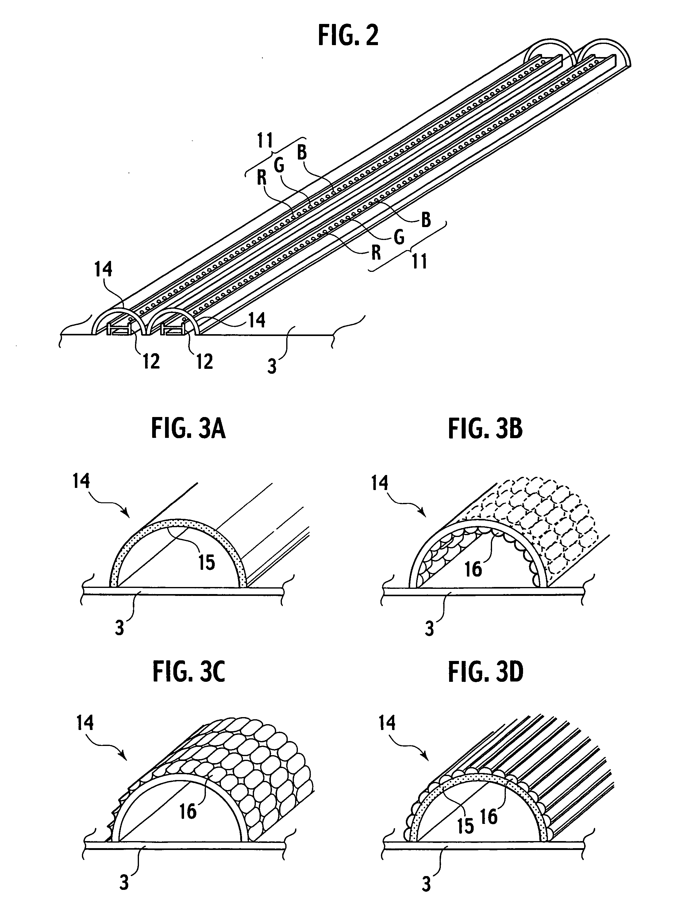
[0067]FIG. 5 is a perspective view showing another profile of the diffuse transmission member 14 in the surface light source device, in accordance with the present invention.

[0068] In the first embodiment mentioned above, the diffuse transmission member 14 is shaped so as to have a semicircular cross section along a direction perpendicular to the point-source line. In detail, the cross section of the diffuse transmission member 14 is shaped so as to draw a semicircle having radii of substantially equal distances in terms of a distance between a light emission surface (exit surface) of the light emission diode 11 and the diffuse transmission member 14. Besides, the diffuse transmission member 14 may be tunnel-shaped so that an exit angle of the illumination lights from the light emission diodes 11 into the light mixing chamber gets larger. For instance, as shown in FIG. 5, the diffuse transmission member 14 may be shaped to have a polygonal cross section along a direction perpendicul...

embodiment

3rd. Embodiment

[0069]FIG. 6 is a perspective view showing a further profile of the diffuse transmission member 14 in the surface light source device, in accordance with the third embodiment of the present invention.

[0070] Again, FIG. 6 also shows an arrangement where the light emission diodes 11 are not arranged at regular intervals but rather in “block form” with respect to each combination of a certain number of colored lights. In this case, the diffuse transmission member 14 is semispherical-shaped so as to cover each light emission diode 11 with respect to each block, in a position where diffuse transmission member's distances from the block become substantially equal to each other. Note that reference numeral 12 denotes a substrate mounting the light emission diode 11.

4th. Embodiment

[0071]FIG. 7 is a perspective view showing a still further profile of the diffuse transmission member 14 in the surface light source device, in accordance with the fourth embodiment of the presen...


PUM


Abstract

A surface light source device 1 includes a base member 3 provided with a plurality of point-source lines, each of which has a plurality of point sources 11 arranged in a line, and a plurality of diffuse transmission members 14 for covering the point-source lines. Each of the diffuse transmission members 14 is located while keeping substantially equal distances from the respective point sources 11 at least in a direction perpendicular to each of the point-source lines. Consequently, it is possible to allow light fluxes emitted from the point sources 11 to be transmitted in diffusion through the diffusion transmission members 14.

Description

BACKGROUND OF THE INVENTION [0001] 1. Field of the Invention [0002] The present invention relates to a surface light source device used in a non-emission display device or the like, and more particularly, relates to a surface light source device using point sources, such as light emission diodes (LED). [0003] 2. Description of the Related Art [0004] There has been proposed a non-emission display device as represented by a liquid crystal display device. This non-emission display device is provided, behind a liquid crystal display device, with a surface light source device (backlight unit) for illuminating it. [0005] Regarding such a surface light source device, Japanese Utility Model Registration No. 2578529 discloses a surface light source device having an optical waveguide that is adapted so as to take light from a light source through a side portion (incident surface) of the optical waveguide and to radiate the light as illumination light from a front portion (exit surface) of the...

Claims


Application Information

Patent Timeline
IPC IPC(8): G09F13/04H01L33/58H01L33/60
CPCG09F13/04G02F1/133606Y10S362/80
Inventor SEGAWA, MASARU
Owner JVC KENWOOD CORP A CORP OF JAPAN
Why Eureka
Try Eureka