
Planar lighting device and a method of producing the same

a lighting device and planar technology, applied in lighting and heating devices, instruments, mechanical devices, etc., can solve the problems of increasing luminance unevenness, increasing luminance unevenness, and inability so as to achieve uniform illumination, increase luminance unevenness, and increase luminance uneven

Inactive Publication Date: 2011-07-21
FUJIFILM CORP
View PDF20 Cites 14 Cited by
  • Summary
  • Abstract
  • Description
  • Claims
  • Application Information

AI Technical Summary

Benefits of technology

[0019]Further, with a configuration wherein the light guide plate containing scattering particles dispersed therein is also provided with the pattern on the top surface or the opposite side thereto, the luminance in a region close to the light entrance plane relatively increases, although such a configuration provides increased freedom in adjusting the luminance distribution of the emission light emitted from the light guide plate. Further, because the pattern is provided close to the light entrance plane, the light is emitted without sufficient diffusion, and hence the unevenness in luminance increases, making it impossible to achieve uniform illumination.
[0020]An object of the present invention is to provide a planar lighting device using a large and thin light guide plate and yet capable of yielding a high light use efficiency, emitting light with a minimized unevenness in luminance, and guiding the admitted light deep into the light guide plate to achieve a luminance distribution that is high in a range near the middle, thereby overcoming the problems associated with the prior art described above.
[0021]The present invention enables emission of light with a high light use efficiency and minimized unevenness in luminance and guidance of the admitted light deep into the light guide plate, achieving luminance that is evenly distributed or a luminance distribution that is uniform or high in a range near the middle.

Problems solved by technology

However, when a part of the pattern-bearing surface is made flat near the light entrance plane as described in JP 2006-294256 A, JP 2004-6187 A, and JP2009-117349 A, the light emitted from the flat surface or a region close to the flat surface, where light is not diffused, exhibits increased unevenness in luminance caused by light sources disposed at intervals among other reasons, making it impossible to achieve uniform illumination.
Further, because the pattern is provided close to the light entrance plane, the light is emitted without sufficient diffusion, and hence the unevenness in luminance increases, making it impossible to achieve uniform illumination.

Method used


Image

  • Planar lighting device and a method of producing the same
  • Planar lighting device and a method of producing the same
  • Planar lighting device and a method of producing the same

Examples


Embodiment Construction

[0035]Now, the planar lighting device of the invention will be described in detail below referring to preferred embodiments illustrated in the accompanying drawings.

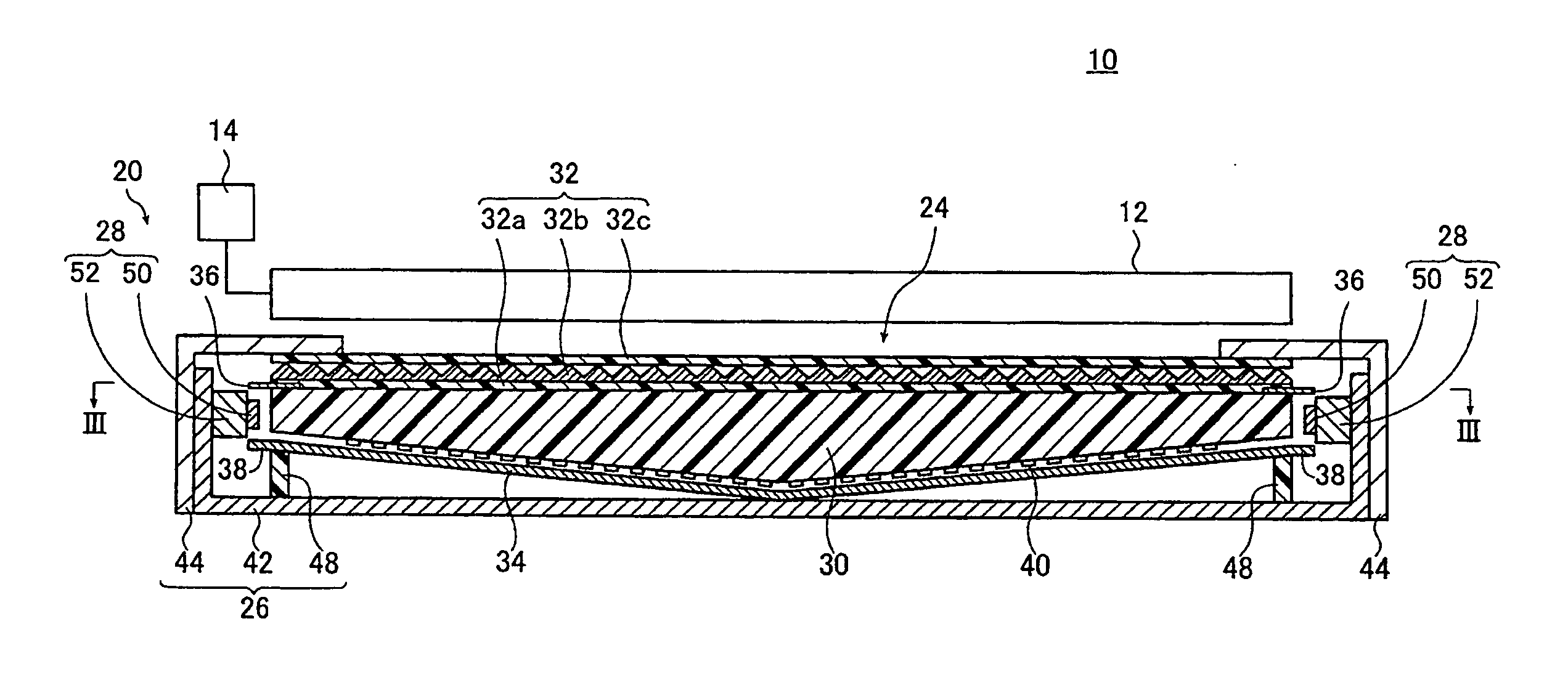
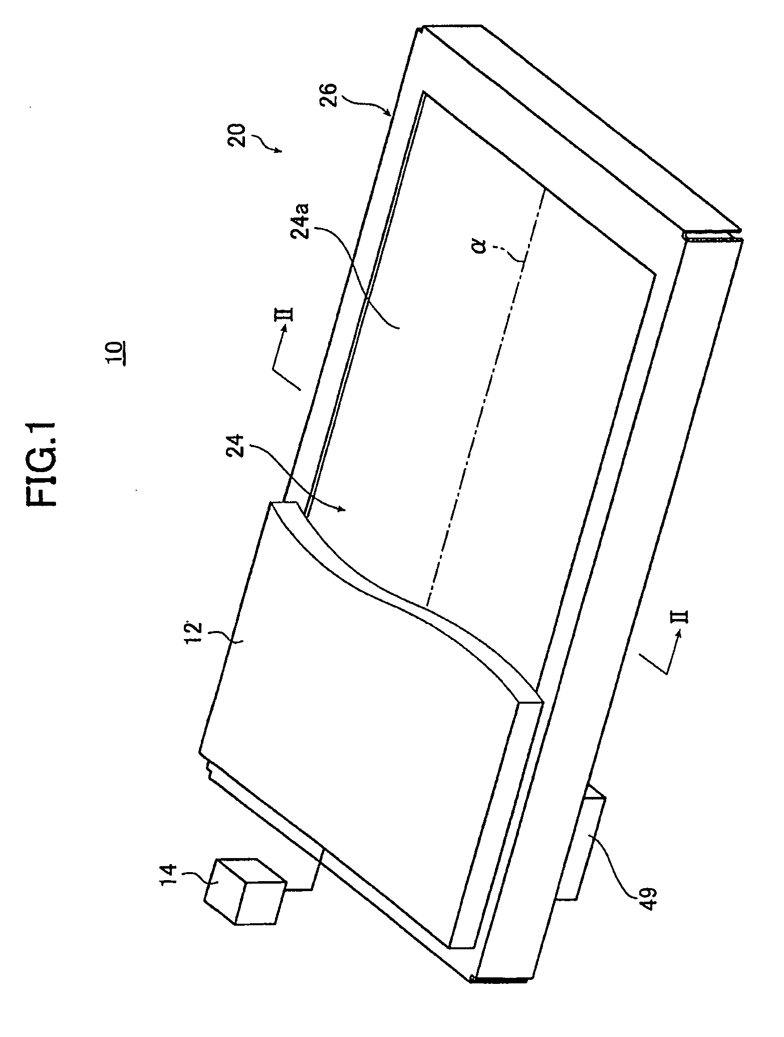
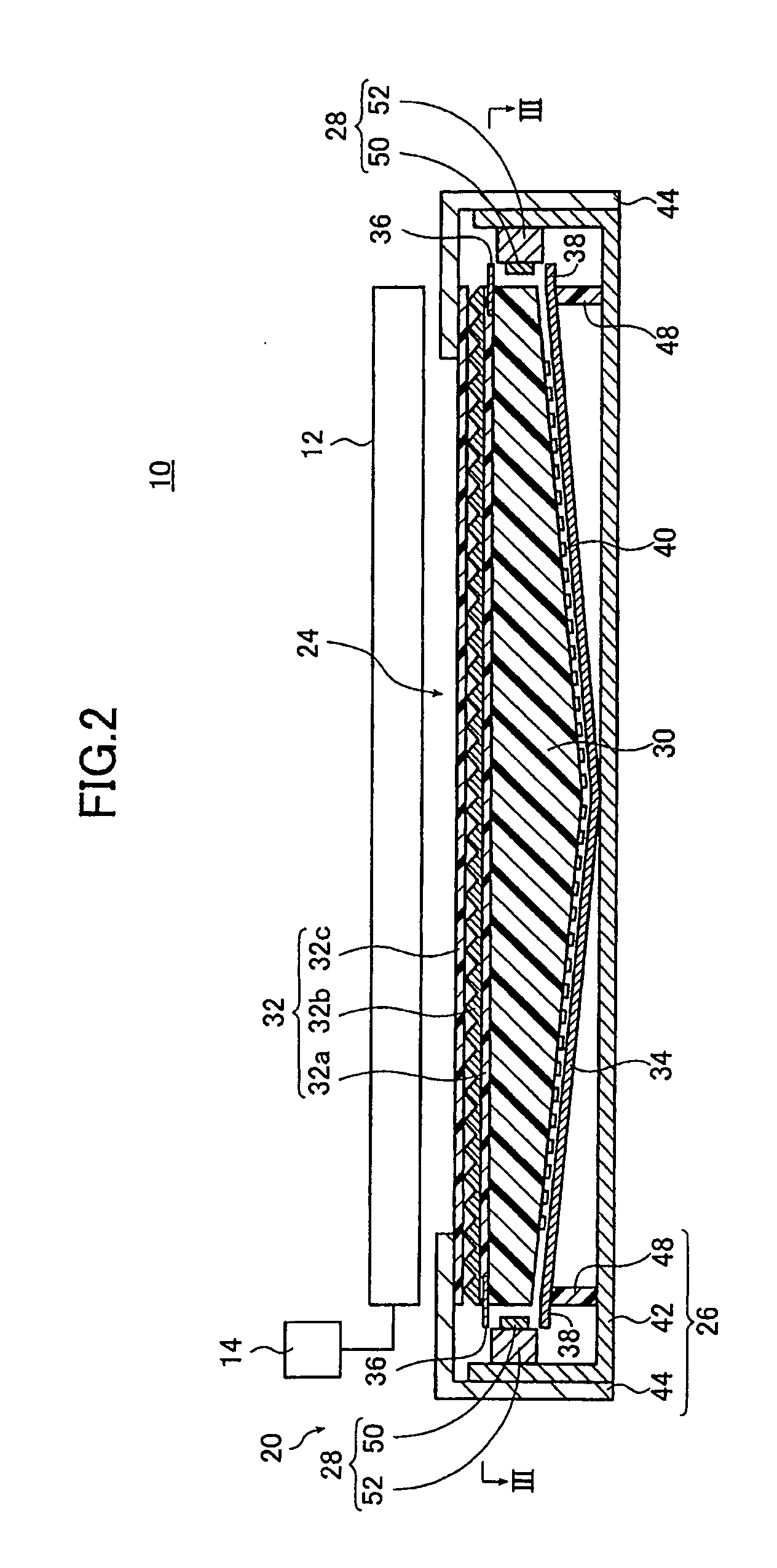
[0036]FIG. 1 is a schematic perspective view illustrating a liquid crystal display device provided with the planar lighting device of the invention; FIG. 2 is a cross-sectional view of the liquid crystal display device illustrated in FIG. 1 taken along line II-II.

[0037]FIG. 3A is a view of an example of the planar lighting device (also referred to as “backlight unit” below) illustrated in FIG. 2 taken along line FIG. 3B is a cross sectional view of FIG. 3A taken along line B-B.

[0038]A liquid crystal display device 10 comprises a backlight unit 20, a liquid crystal display panel 12 disposed on the side of the backlight unit closer to the light exit plane, and a drive unit 14 for driving the liquid crystal display panel 12. In FIG. 1, a part of the liquid crystal display panel 12 is not shown to illustrate the configuratio...


PUM


Abstract

A planar lighting device in which transmittance adjusting members are not provided in a region extending a distance of Lmfp from an end of the light guide plate closer to the light entrance plane in a direction normal to the light entrance plane, where Lmfp is a mean free path of luminous flux emitted from the light source and admitted in the light guide plate through the light entrance plane.

Description

BACKGROUND OF THE INVENTION[0001]The present invention relates to a planar lighting device used for a liquid crystal display device and the like and a method of manufacturing the same.BACKGROUND ART[0002]Liquid crystal display devices use a backlight unit for radiating light from behind the liquid crystal display panel to illuminate the liquid crystal display panel. A backlight unit is configured using a light guide plate for diffusing light emitted by an illumination light source to irradiate the liquid crystal display panel and optical parts such as a prism sheet and a diffusion sheet for rendering the light emitted from the light guide plate uniform.[0003]Currently, large liquid crystal televisions predominantly use a so-called direct illumination type backlight unit comprising a light guide plate disposed immediately above the illumination light source. This type of backlight unit comprises a plurality of cold cathode tubes serving as a light source provided behind the liquid cr...

Claims


Application Information

Patent Timeline
Patent Type & Authority Applications(United States)
IPC IPC(8): F21V8/00
CPCG02B6/0041G02B6/0043G02B6/0046G02F1/133615G02B6/0068G02B6/0073G02F1/133603G02B6/0055
Inventor IWASAKI, OSAMU
Owner FUJIFILM CORP
Learn More