

Self-standing reflector for a luminaire
- Summary
- Abstract
- Description
- Claims
- Application Information
AI Technical Summary
Benefits of technology
Problems solved by technology
Method used
Image

Examples
Embodiment Construction
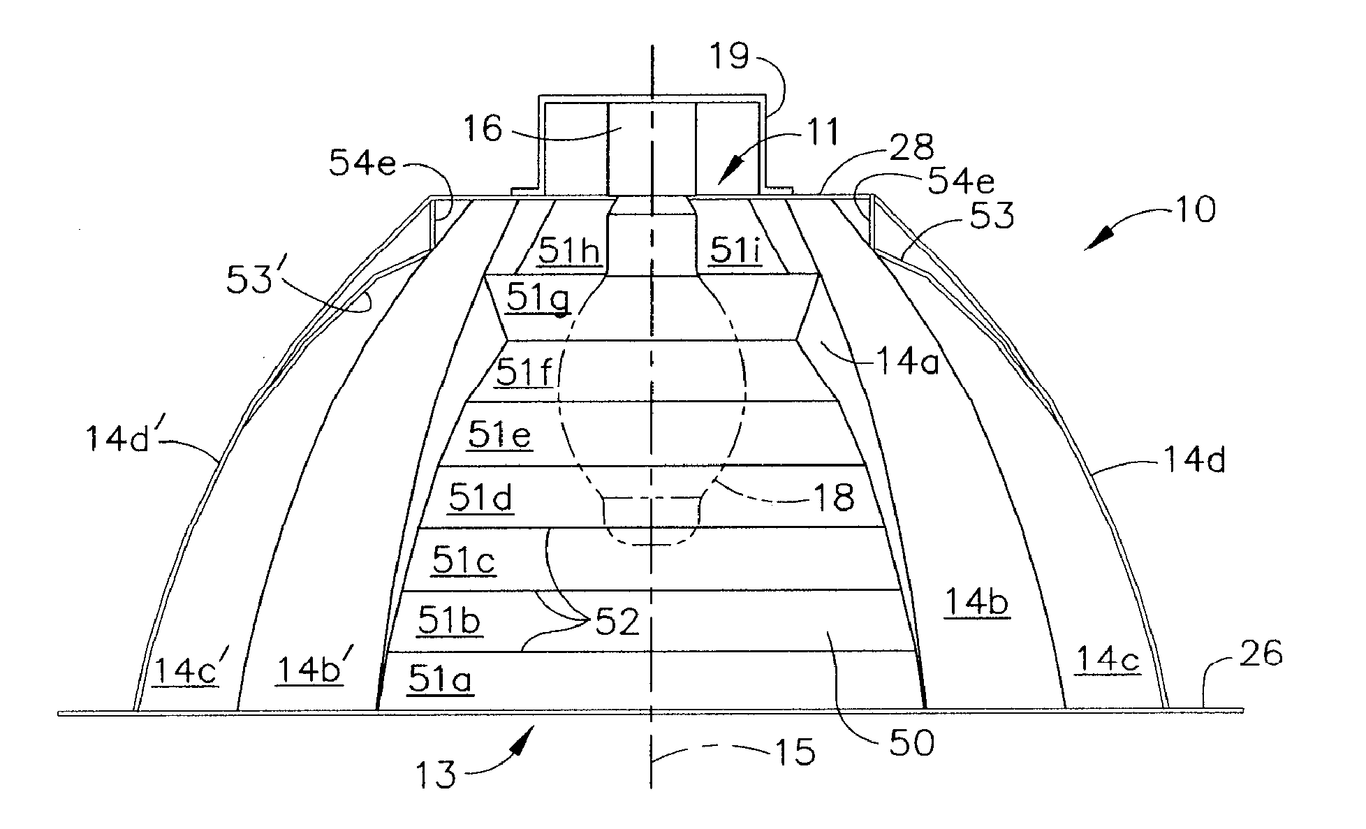
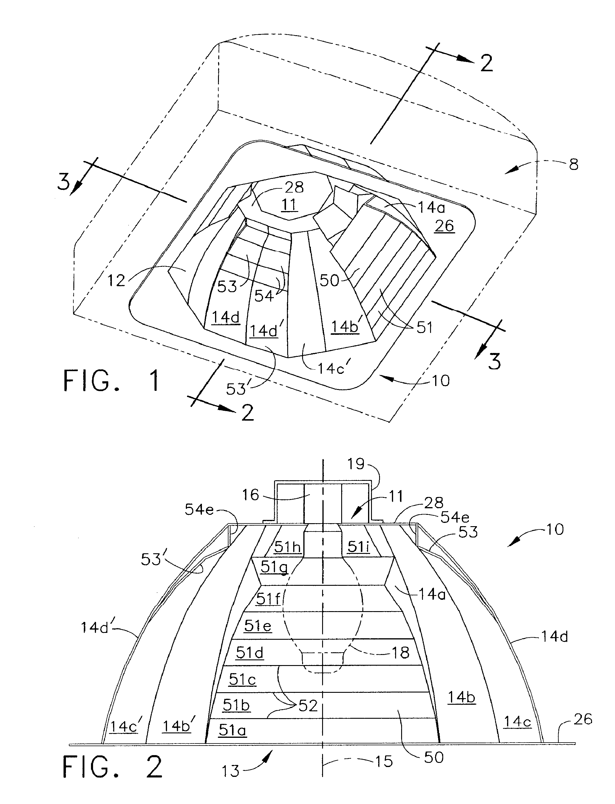
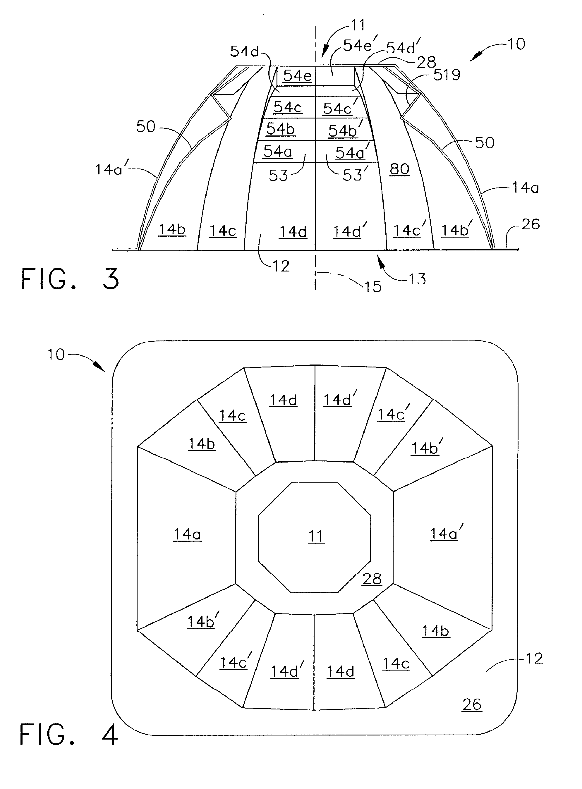
[0051] The main reflector of the self-standing reflector of the present invention has an interior reflective surface that is formed to reflect light from a lamp disposed within a cavity formed by the main reflector. The interior reflective surface is configured to reflect efficiently the light that is emitted from a lamp through the light-emitting opening of the luminaire, either directly or off of another reflector panel. Typically, the main reflector can bc a conventional reflector for reflecting light from a lamp through the opening of the luminaire in which it is disposed. The typical reflector comprises a plurality of reflector panels that are retained in relationship with one another into a predetermined three-dimensional reflector shape. The plurality of reflector panels are typically retained into the predetermined three-dimensional reflector shape using a securement means.
[0052] The main reflector can be fabricated by molding or otherwise forming a flat piece of metal or o...
PUM
 Abstract
Description
Claims
Application Information