OFDM demodulating apparatus and method

a demodulating apparatus and frequency division technology, applied in the field of orthogonal frequency division multiplexing (ofdm) demodulating apparatus and method, can solve the problems of affecting the transmission path characteristic, causing the creation of wrong delay profile, and prone to terrestrial broadcasting

Inactive Publication Date: 2007-03-29
SONY CORP
View PDF6 Cites 41 Cited by
  • Summary
  • Abstract
  • Description
  • Claims
  • Application Information

AI Technical Summary

Benefits of technology

[0023] Accordingly, it is desirable to propose an OFDM demodulating apparatus and method thereof that allows the occurrence of the trigger to an FFT window based on a right delay profile even in an atmosphere in motion.

Problems solved by technology

In other words, terrestrial broadcasting is susceptible to the interference by delay waves due to the surroundings such as the surrounding geography and buildings at the receiving point, and the signal received by an OFDM receiving apparatus becomes a composite wave resulting from the combination of multiple delay waves.
However, in an atmosphere in motion, the transmission path characteristic fluctuates at a high Doppler frequency, and a wrong delay profile might be created when the time-direction interpolation processing does not satisfy the sampling theorem.
On the other hand, as shown in FIG. 15B, when the time-dependent fluctuation of the transmission path does not satisfy the sampling theorem, the interpolation value (circles in white) of the SP signals (circles in black) do not agree with the real transmission path characteristic, resulting in the wrong estimation of the transmission path characteristic as indicated by the shown broken line.
Furthermore, in an atmosphere in motion, the precision of the estimation of delay profiles also decreases when the SNR (Signal to Noise Ratio) is deteriorated by a factor such as a fall of signal power.

Method used


Image

  • OFDM demodulating apparatus and method
  • OFDM demodulating apparatus and method
  • OFDM demodulating apparatus and method

Examples


Embodiment Construction

[0043] An OFDM receiving apparatus under ISDB-T (Integrated Services Digital Broadcasting-Terrestrial) standard according to embodiments of the invention will be described below.

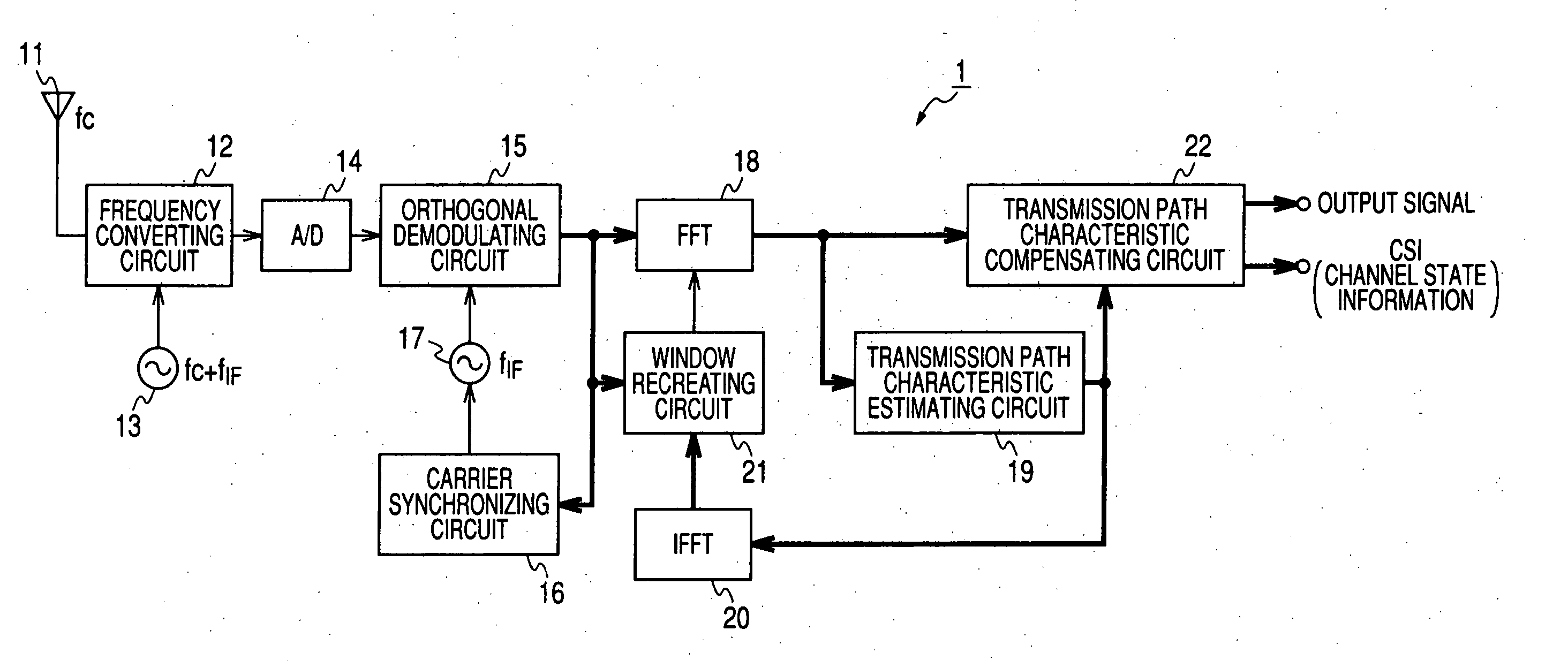
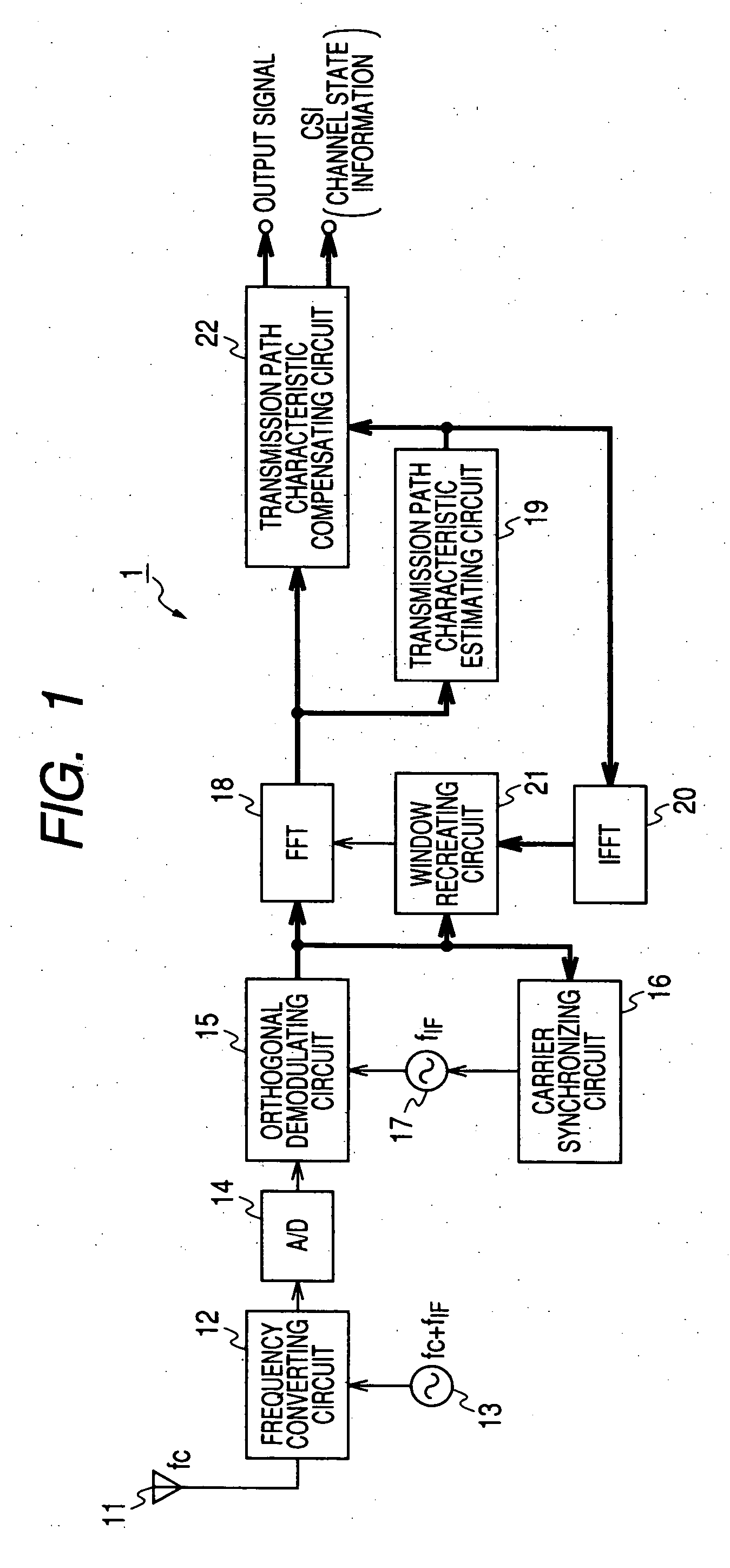
[0044]FIG. 1 shows a block construction diagram of an OFDM receiving apparatus 1 according to an embodiment of the invention. Here, the thick lines indicate a signal component when the signal transmitted between blocks is a complex signal while the thin lines indicate a signal component when the signal transmitted between blocks is a real signal.

[0045] The OFDM receiving apparatus 1 includes, as shown in FIG. 1, an antenna 11, a frequency converting circuit 12, a local oscillator 13, an A / D converting circuit 14, an orthogonal demodulating circuit 15, a carrier synchronizing circuit 16, a local oscillator 17, an FFT calculating circuit 18, a transmission path characteristic estimating circuit 19, an IFFT calculating circuit 20, a window recreating circuit 21 and a transmission path characteristic compensat...


PUM


Abstract

An orthogonal frequency division multiplexing (OFDM) demodulating apparatus includes a delay profile creating section, a Fourier converting section, a pilot signal extracting section, a transmission path characteristic estimating section, an inverse Fourier converting section, and a window control section. In this case, the window control section creates a delay profile for defining a calculation range by leaving a path which exists at a same position in both the delay profiles created by the delay profile creating section and the inverse Fourier converting section and the number of times of detection which is equal to or higher than a threshold value and defines a higher threshold value for the path at a predetermined position from the position of the main path within the delay profile created by the inverse Fourier converting section than for the paths at the other positions.

Description

CROSS-REFERENCE TO RELATED APPLICATIONS [0001] The present application claims priority from Japanese Patent Application No. JP 2005-208679 filed on Jul. 19, 2005, the disclosure of which is hereby incorporated by reference herein. BACKGROUND OF THE INVENTION [0002] 1. Field of the Invention [0003] The present invention relates to an orthogonal frequency division multiplexing (OFDM) demodulating apparatus and method thereof that demodulates an OFDM signal. [0004] 2. Description of the Related Art [0005] In recent years, a modulating method called Orthogonal Frequency Division Multiplexing method (called OFDM method hereinafter) has been proposed for modulating digital data. In OFDM method, data is assigned and is digitally modulated to the amplitude and phase of each of many orthogonal sub-carriers within a transmission band by PSK (Phase Shift Keying) or a QAM (Quadrature Amplitude Modulation). [0006] OFDM method has been widely considered to apply to terrestrial digital broadcastin...

Claims


Application Information

Patent Timeline
Patent Type & Authority Applications(United States)
IPC IPC(8): H04J11/00
CPCH04L25/0232H04L27/261H04L27/2665H04L27/2662H04L27/265H04L27/26526H04L27/26
Inventor KAWAUCHI, HIDETOSHIHYAKUDAI, TOSHIHISAOKAMOTO, TAKUYAYAJIMA, ATSUSHIYAMAGATA, TAKUYAMAMOTO, KAZUTAKAKAWABATA, SHIGENARI
Owner SONY CORP
Why Eureka
Try Eureka