Sensing apparatus, program execution apparatus and image-taking system
- Summary
- Abstract
- Description
- Claims
- Application Information
AI Technical Summary
Benefits of technology
Problems solved by technology
Method used
Image
Examples
example 1
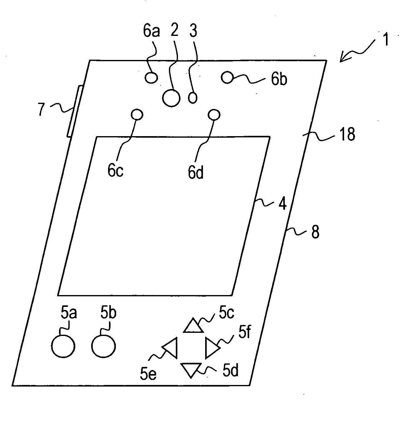
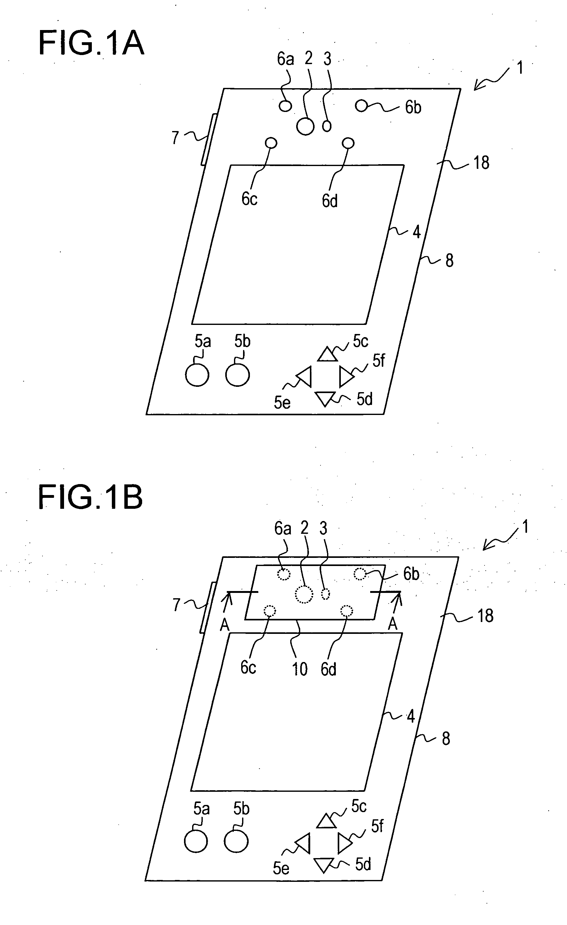
[0080] First, Example 1 will be described. In Example 1, the attachment 10 is fitted to the case 8. FIG. 4A is an enlarged perspective view of the peripheral portion of the attachment 10 with the upper plate 40 removed. FIG. 4B is a sectional view of the attachment 10, taken along line A-A of FIG. 1B. Note that the case 8 is omitted and thus not shown in FIG. 4A, and that the camera 2, the LED 3, and the case 8 are omitted and thus not shown in FIG. 4B.
[0081] The attachment 10 is so structured as to have: fitting rods 9a, 9b, 9c, and 9d which fit with fitting holes 6a, 6b, 6c, and 6d, respectively; an upper plate 40; a lower plate 44; and a globe 41 of a spherical shape as a moving body. The fitting rods 9a, 9b, 9c, and 9d are formed of, for example, resin material.
[0082] The lower plate 44 has a shape of a rotational parabolic curve with a cross section drawing a parabolic curve, like a reflecting mirror of a parabolic antenna. On the concave surface of the lower plate 44, the gl...
example 2
[0100] Next, Example 2 will be described. In Example 2, the attachment 10a is fitted to the case 8. FIG. 7 is an enlarged perspective view of the peripheral portion of the attachment 10a. Note that the case 8 is omitted and thus not shown in FIG. 7.
[0101] The attachment 10a is so structured as to have: fitting rods 9a, 9b, 9c, and 9d; and a drawing surface 55. The drawing surface 55 is a plate-like body having a square shape as viewed from above, and fixed at the peripheral part thereof to the fitting rods 9a, 9b, 9c, and 9d. The drawing surface 55 and the top surface 18 of the case 8 are substantially parallel to each other. A game apparatus of Example 2 has a pen 56 of a rod-like shape which is used simultaneously with the attachment 10a. One end of the pen 56 is provided with a pen tip 57. To use the pen 56, the user brings the pen tip 57 into contact with an arbitrary point on an upper surface (on the side opposite to the case 8) of the drawing surface 55.
[0102] The camera 2 p...
example 3
[0111] Next, Example 3 will be described. In Example 3, the attachment 10b is fitted to the case 8. FIG. 8A is an enlarged perspective view of the peripheral portion of the attachment 10b with an upper plate 60 removed. FIG. 8B is a sectional view of the attachment 10b, taken along line A-A of FIG. 1B. Note that the case 8 is omitted and thus not shown in FIG. 8A, and that the camera 2, the LED 3, and the case 8 are omitted and thus not shown in FIG. 8B. Also note that the line A-A does not extend across a magnet 61.
[0112] The attachment 10b is so structured as to have: fitting rods 9a, 9b, 9c, and 9d; the upper plate 60; the magnet 61; and a lower plate 62.
[0113] The lower plate 62 is a discoid plate having a shape of a circle as viewed from above. At the center of the surface of the lower plate 62 on the side opposite to the case 8, a magnet support part 63 is formed in a protruding manner. The magnet 61 is a compass having a square shape as viewed from above, and is arranged ab...
PUM
 Abstract
Description
Claims
Application Information
 - R&D
- Intellectual Property
- Life Sciences
- Materials
- Tech Scout
- Unparalleled Data Quality
- Higher Quality Content
- 60% Fewer Hallucinations
Browse by: Latest US Patents, China's latest patents, Technical Efficacy Thesaurus, Application Domain, Technology Topic, Popular Technical Reports.
© 2025 PatSnap. All rights reserved.Legal|Privacy policy|Modern Slavery Act Transparency Statement|Sitemap|About US| Contact US: help@patsnap.com


