Electronic camera having improved focus performance

Inactive Publication Date: 2007-03-29
FUJIFILM CORP +1
View PDF15 Cites 27 Cited by
  • Summary
  • Abstract
  • Description
  • Claims
  • Application Information

AI Technical Summary

Benefits of technology

[0016] According to the present invention, perspective is emphasized and is expressed on the monitor like a single-lens reflex. Since a user can easily recognize a focu

Problems solved by technology

However, since a pixel number of the LCD panel is extremely small in comparison with that of the image sensor, the image displayed thereon is grainy and it is difficult to finely perform the focus adjustment.
Moreover, when the LCD panel is used, quality of the viewfinder image displayed thereon further deteriorates due to dropping frames of the subject image continuously displayed.
However, some of the abov

Method used


Image

  • Electronic camera having improved focus performance
  • Electronic camera having improved focus performance
  • Electronic camera having improved focus performance

Examples


Embodiment Construction

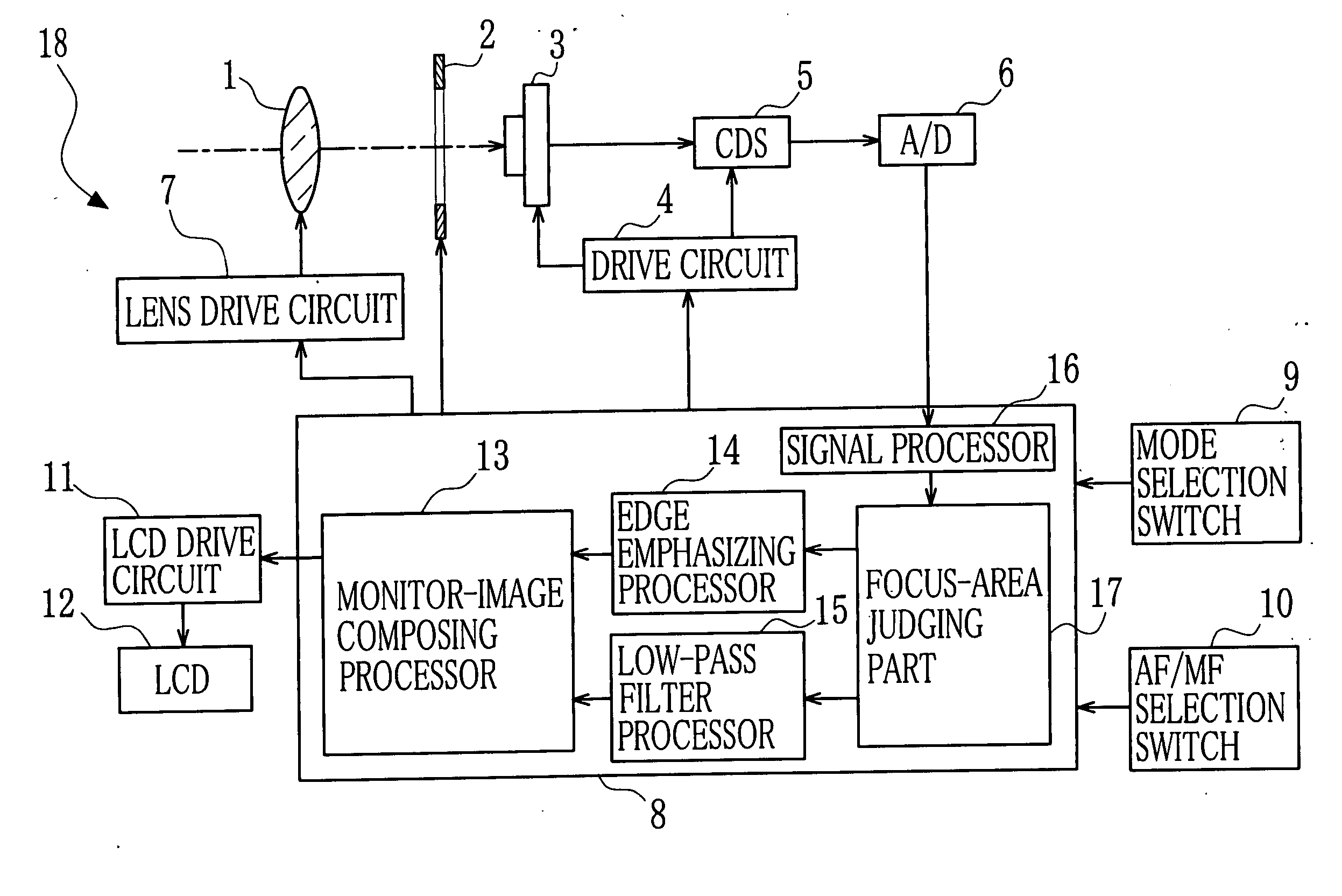
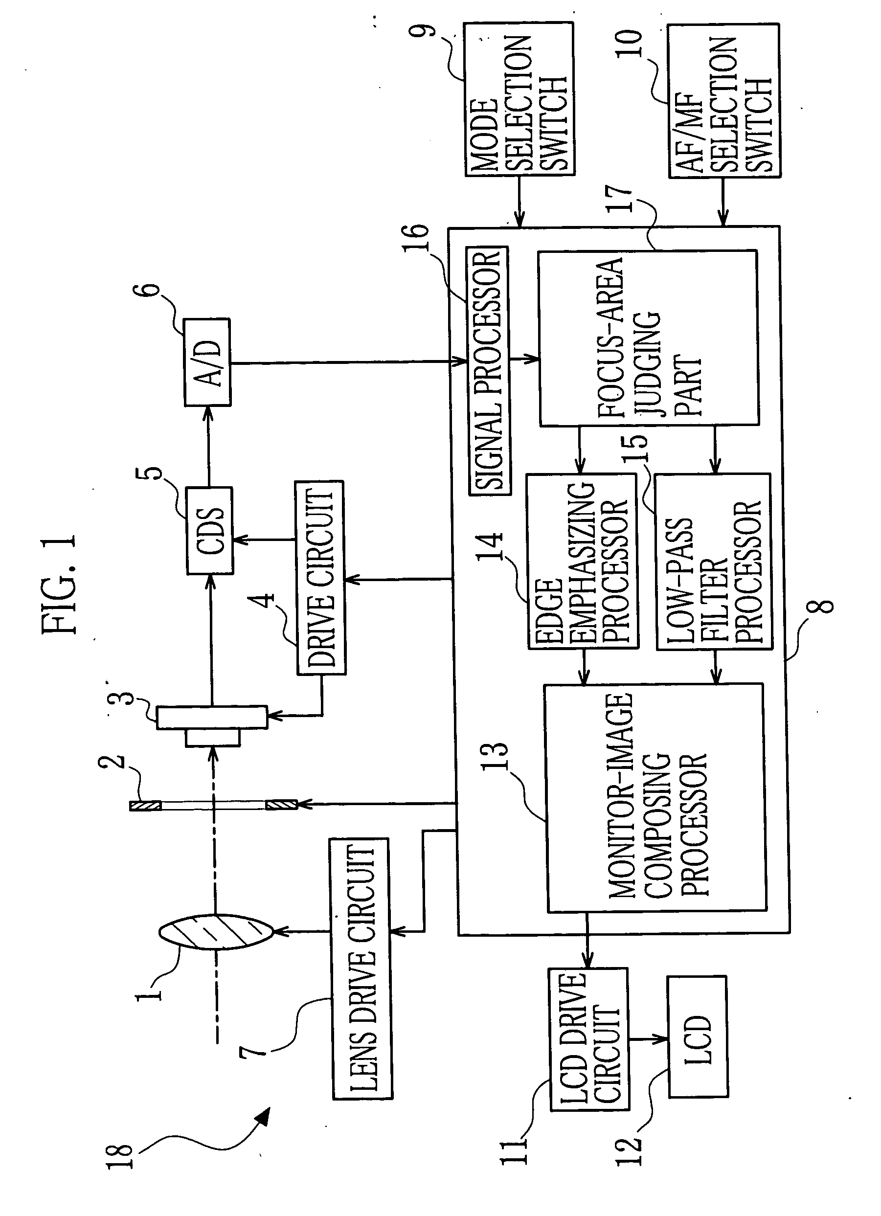
[0025] An embodiment of the present invention is described below with reference to drawings. FIG. 1 is a block diagram showing an electrical structure of an electronic camera according to the present invention. In FIG. 1, a CCD image sensor 3 is disposed behind a taking lens 1 and a mechanical shutter 2. The taking lens 1 for focusing subject light on the CCD image sensor 3 is adapted to be moved to a focal position by a lens drive circuit 7, which is activated in response to a control signal outputted from a central control circuit 8. Meanwhile, a shutter speed and shutter timing of the mechanical shutter 2 are set in response to a control signal which is outputted from the central control circuit 8 in association with timing of a release operation of a user.

[0026] The CCD image sensor 3 converts an optical image of a subject, which is formed on pixels of the CCD image sensor 3, into an electronic signal. In other words, the CCD image sensor 3 performs photoelectric conversion. A ...


PUM


Abstract

An image is divided into areas in accordance with degrees of focusing. As the divided areas, there are a focus area and a non-focus area. With respect to the non-focus area, the image thereof is processed so as to emphasize its blur. In contrast, with respect to the focus area, the image thereof is processed so as to emphasize its sharpness. The processed image is displayed on a monitor so that perspective is expressed like a single-lens reflex.

Description

FIELD OF THE INVENTION [0001] The present invention relates to an electronic camera in which focus performance is improved by emphasizing perspective of an image displayed on an LCD. BACKGROUND OF THE INVENTION [0002] In recent years, electronic cameras are popularly used. In this kind of the electronic camera, image data captured by means of a CCD image sensor and so forth is converted into digital data and is stored in a memory. Meanwhile, storage capacity of the memory increases in accordance with high integration thereof and moving-image compression technique is improved so that it becomes possible to take a moving image. Consequently, some of the commercial electronic cameras are capable of performing both of still-image shooting and moving-image shooting. [0003] When shooting is performed with the electronic camera, it is possible to utilize an LCD panel as an electronic viewfinder besides a built-in optical viewfinder. On the LCD panel, a subject image formed on the CCD image...

Claims


Application Information

Patent Timeline
IPC IPC(8): G03B13/34
CPCG03B17/14H04N5/262H04N5/23212H04N23/673H04N23/63
Inventor SENBA, TAKEHIKO
Owner FUJIFILM CORP
Why Eureka
Try Eureka