Temperature Control Device of Simple Cooling Fan

Inactive Publication Date: 2007-03-29
LIN TRAIN
View PDF5 Cites 6 Cited by
  • Summary
  • Abstract
  • Description
  • Claims
  • Application Information

AI Technical Summary

Benefits of technology

[0007] It is therefore an object of the invention to solve the afore-mentioned problems. The invention utilizes the simple design of a temperature control device, which is directly attached externally to a cooling fan motor, for detecting the temperature variation of an electronic element so as to control voltage drops and reduce rotational speeds of the fan motor.
[0008] In addition to achieving the control abilities similar to that of a MCU in low costs, the temperature control device of a cooling fan also reduces the overall physical size, thus suitable for use in compact electronic devices.

Problems solved by technology

Due to high density and high computation power of electronic components, a lot of heat is generated during device operation.
However, the traditional temperature-controlled speed adjustment design of cooling fans are physically limited in size due to the structural nature of the electronic elements and wires, and can not be reduced to less than 6 cm.
Hence, the traditional model does not satisfy the current design trend for lightweight and compact electronics.
Also, the servo control of traditional cooling fan does not reach a fast, stable, and flawless state.
Although the use of a MCU may solve such a problem, the implementation of a MCU means a 2 to 3 times increase in costs as compared to a traditional architecture, and works in no favor to bring down the manufacturing size to less than 6 cm.

Method used


Image

  • Temperature Control Device of Simple Cooling Fan
  • Temperature Control Device of Simple Cooling Fan
  • Temperature Control Device of Simple Cooling Fan

Examples


Embodiment Construction

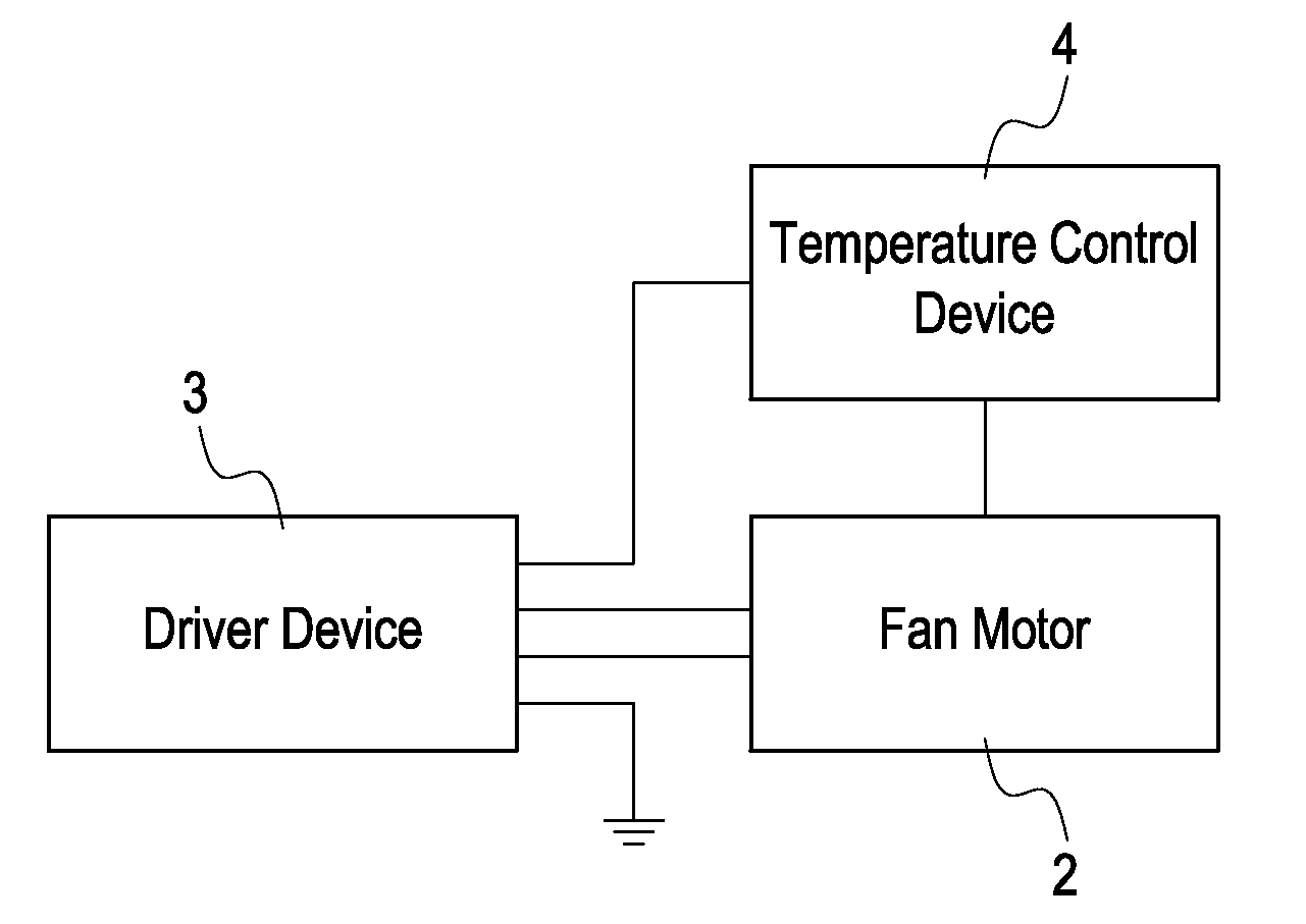
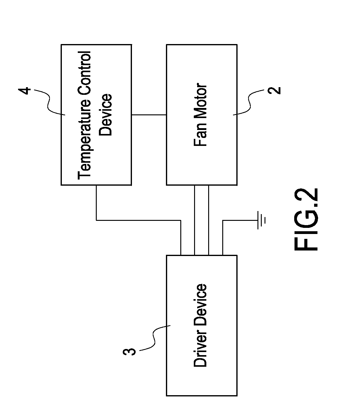
[0015]FIG. 2 is schematic illustrating the architecture of a simple temperature control device in a half-wave configuration according to a preferred embodiment of the invention. FIG. 3 is a circuit schematic illustrating a simple temperature control device according to a preferred embodiment of the invention. As shown in FIGS. 2 and 3, the temperature control device of a simple cooling fan includes a fan motor 2, a driver device 3, and a temperature control device 4 collectively forming a simple, low-cost temperature control device as an external add-on of a cooling fan, allowing the overall size of the cooling fan to be manufactured less than 4 cm, and achieving temperature control capability near that of a MCU.

[0016] The coils L1 and L2 of the above described fan motor 2 are electrically connected to, and driven by, the driver device 3.

[0017] The output terminal of driver device 3 is connected to coils L1 and L2 of fan motor 2. Driver device 3 detects a rise in temperature of th...


PUM


Abstract

A temperature control device of a simple cooling fan includes a fan motor, a driver device, and a temperature control device. The driver device is electrically connected to the fan motor. The temperature control device is electrically connected to the fan motor and the driver device. The driver device detects the temperature rise variation of the electronic element and drives the fan motor to rotate in high speed. When the fan motor remains in high rotational speed as the temperature of the electronic element decreases, a voltage-drop signal is generated to drive the fan motor to its reduce rotational speed. The temperature control device achieves control abilities similar to that of a MCU, reduces manufacturing costs, and reduces over all physical size of the cooling fan, and is suitable for use in compact electronics.

Description

BACKGROUND OF THE INVENTION [0001] 1. Field of the Invention [0002] The present invention relates to a cooling device, and in particular, to a simple temperature control device of a cooling fan. [0003] 2. Description of Prior Art [0004] Current focus in the IT and consumer electronics industry is on the development of electronic gadgetries with multi-functions, high computational power, and compact size. Due to high density and high computation power of electronic components, a lot of heat is generated during device operation. A cooling mechanism is therefore required to prevent overheat and enable proper circuit operation. The cooling fan plays a major role in a cooling mechanism in generating sufficient wind flow to increase heat exchange rates, thereby accomplishing fast heat dissipation. [0005]FIG. 1 shows schematic illustrating the architecture of a traditional cooling fan 1, which includes a fan motor 11, and a fan driver device 12 for controlling operation of fan motor 11. Fa...

Claims


Application Information

Patent Timeline
IPC IPC(8): F04D15/00H05K7/20
CPCF04D27/004Y02B30/70
Inventor LIN, TRAIN
Owner LIN TRAIN
Why Eureka
Try Eureka