Implant with integral fastener retention

a technology of fastener and implant, which is applied in the field of orthopaedic implants, can solve the problems of increasing the intensity of toque feedback, the inability of all the fasteners in the implant system to work normally, and the difficulty of protruding over each detent, so as to achieve the effect of rapid movemen

Inactive Publication Date: 2007-03-29
CHILDRENS HOSPITAL MEDICAL CENT CINCINNATI
View PDF32 Cites 52 Cited by
  • Summary
  • Abstract
  • Description
  • Claims
  • Application Information

AI Technical Summary

Benefits of technology

[0008] The anti-backout features of the invention provide feedback as they engage, allowing the surgeon to move quickly when placing a fastener without the concern for inadvertent over-tightening. As the protrusions engage, the surgeon feels the engagement as an increase in torque and an immediate drop-off of torque as the protrusions exit one detent and enter another. The toque feedback increases in intensity as the fastener is tightened and it becomes more difficult for the protrusion to ramp up and over each detent.

Problems solved by technology

Such a catastrophic failure of all the fasteners in implant systems is unusual but possible
The toque feedback increases in intensity as the fastener is tightened and it becomes more difficult for the protrusion to ramp up and over each detent.

Method used


Image

  • Implant with integral fastener retention
  • Implant with integral fastener retention
  • Implant with integral fastener retention

Examples


Embodiment Construction

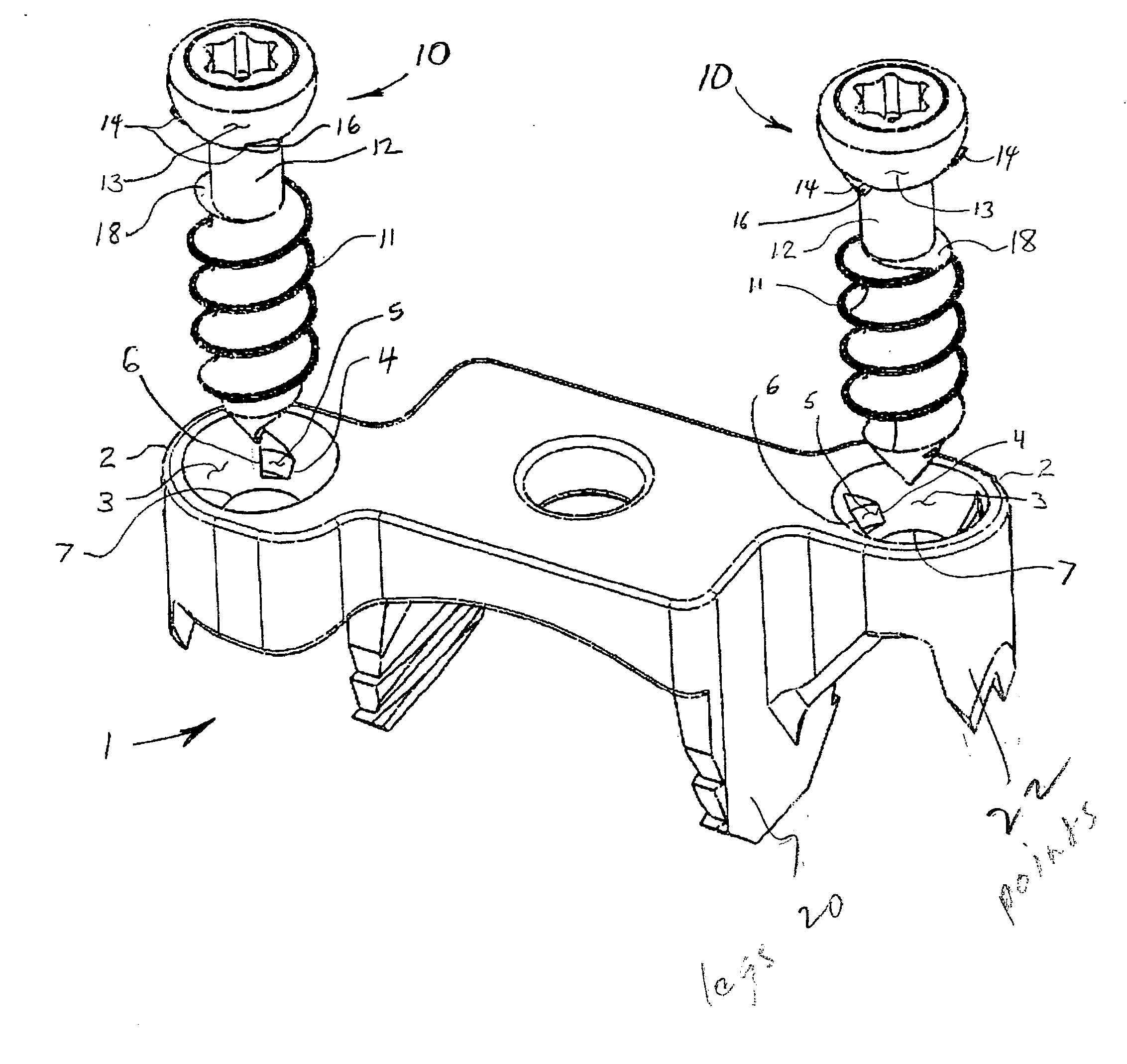
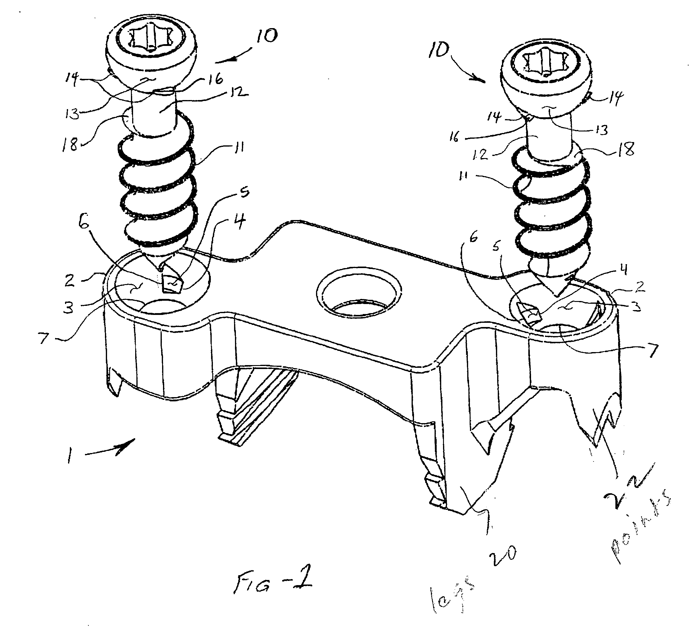
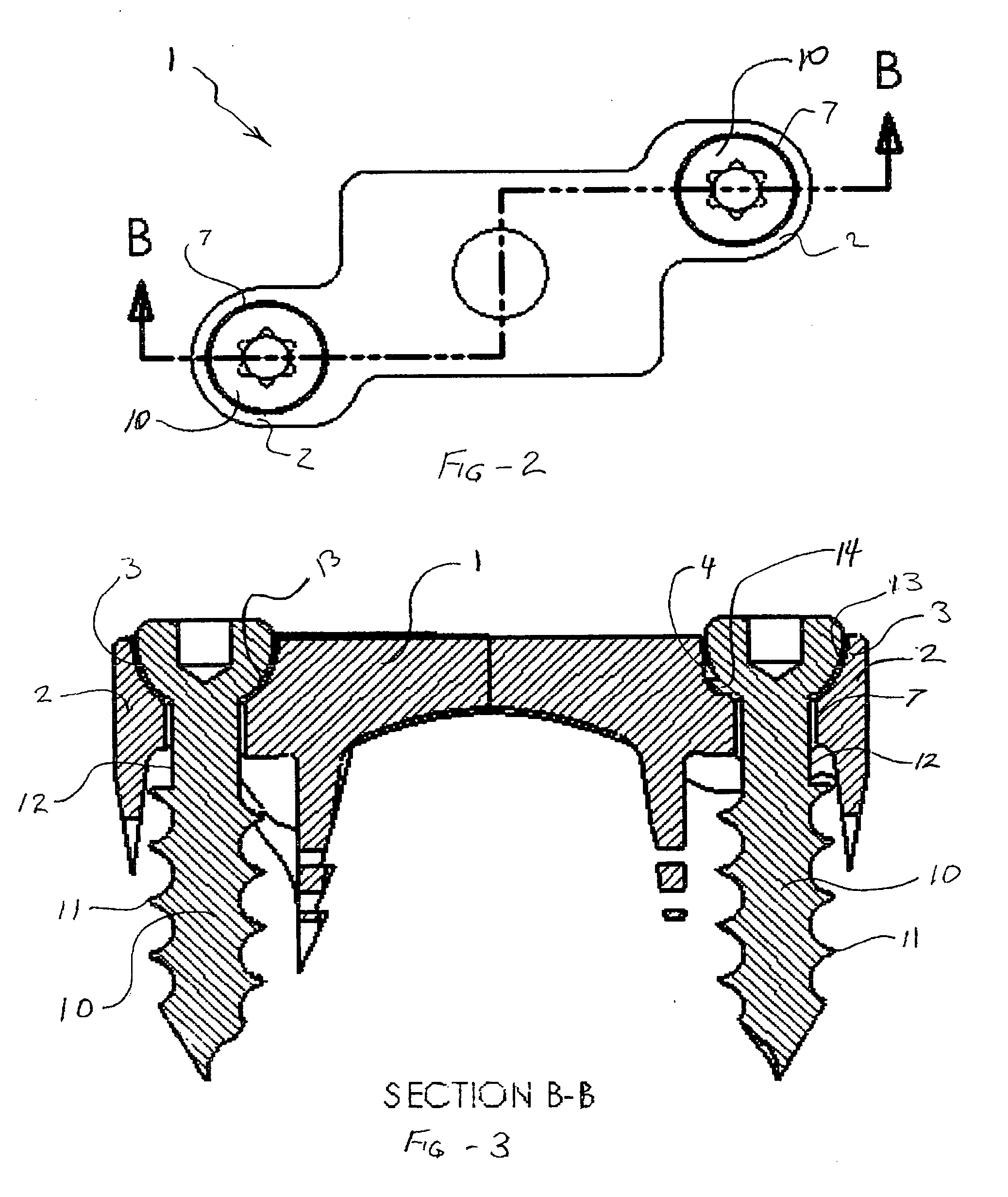
[0015] Referring now to the drawings, FIG. 1 shows the implant (1) having a top surface and a bottom surface with optional barbed, bone-engaging legs (20) pointed sections (22). The implant includes one or more fastener-retaining portions (2) with fastener retaining bores or holes (7). The holes include flared walls where they emerge from the top surface of the implant. In the preferred embodiment, the walls define a hemispherical fastener contact surfaces (3). The surfaces further include one or more recesses (4) having a ramp-like surface (5) and a stop-surface (6).

[0016] One or more fasteners (10) each have a thread (11) and screw thread relief (12) that creates a land (18). The fastener has an outer surface (13) that cooperates with the fastener contact surface in the hole (7) in the retaining portions (2) of the implant (1). Again, the outer surface is preferably hemispherical. Though other combinations may be used, in the preferred embodiment the system uses three projections...


PUM


Abstract

An orthopaedic implant provides a simple yet effective retention system requiring no additional components beyond the implant and the associated fastener(s). A plurality of anti-rotation protrusions on the fastener or screw head that match recesses in the implant. The protrusions engage the recesses to prevent the fastener from reversing direction, thereby assuring that the associated fastener does not backout during normal motion of the spine and other anatomical structures. A land on the fastener screw thread assures the fastener will not disengage from the implant should it strip out of the bone. Preventing the fastener from backing out assures it will not detach from the implant or staple, assuring that the implant will remain in place until all fasteners in the system have catastrophically failed. The anti-backout features of the invention provide feedback as they engage, allowing the surgeon to move quickly when placing a fastener without the concern for inadvertent over-tightening. Although ideally suited to a spinal correction system such as a cervical plate, the invention is applicable to other orthopedic devices, including plates and staples for other applications.

Description

FIELD OF THE INVENTION [0001] This invention relates generally to orthopaedic implants and, in particular, to a bone plate having fastener retention features. BACKGROUND OF THE INVENTION [0002] Hemiepiphysiodesis systems are used for the correction, arresting or slowing of abnormal curvature of the spine, including scoliosis, hyperlordosis and hypokyphosis. Such spinal correction systems bridge vertebra that remain active. However, since the vertebral bodies are still in motion, a gradual dislodgment or outward movement of the fastener could result. As with vertebral plates, partial protrusion of one or more fasteners could damage surrounding structures such as the lung (or the esophagus for cervical plate) and, in a worst case scenario, could permit the plate or correction system to dislodge. [0003] Vertebral (e.g. cervical) plates and other spinal correction systems using hemiepiphysiodesis principles and fastener retention are known in the art. U.S. Pat. No. 6,746,450 to Wall et ...

Claims


Application Information

Patent Timeline
Patent Type & Authority Applications(United States)
IPC IPC(8): A61F2/30
CPCA61B17/809A61B17/8052
Inventor REYNOLDS, JOSEPH
Owner CHILDRENS HOSPITAL MEDICAL CENT CINCINNATI
Why Eureka
Try Eureka