
Flared stents and apparatus and methods for delivering them

a stent and flap technology, applied in the field of flap stents, can solve problems such as improper deployment risks, and achieve the effects of enhancing the support of the ostium, sufficient stiffness, and reducing the risk of improper deploymen

Active Publication Date: 2007-03-29
INCEPT LLC
View PDF62 Cites 77 Cited by
  • Summary
  • Abstract
  • Description
  • Claims
  • Application Information

AI Technical Summary

Benefits of technology

The stent design ensures accurate and complete dilation of ostia, reduces the risk of improper deployment, and maintains ostium patency by providing enhanced radial strength and flexibility, facilitating secure positioning and long-term support.

Problems solved by technology

FIGS. 1, 2, and 3 show attempts to deploy flared stents within various ostia having different shapes and / or sizes, and some of the risks of improper deployment.

Method used


Image

  • Flared stents and apparatus and methods for delivering them
  • Flared stents and apparatus and methods for delivering them
  • Flared stents and apparatus and methods for delivering them

Examples


Embodiment Construction

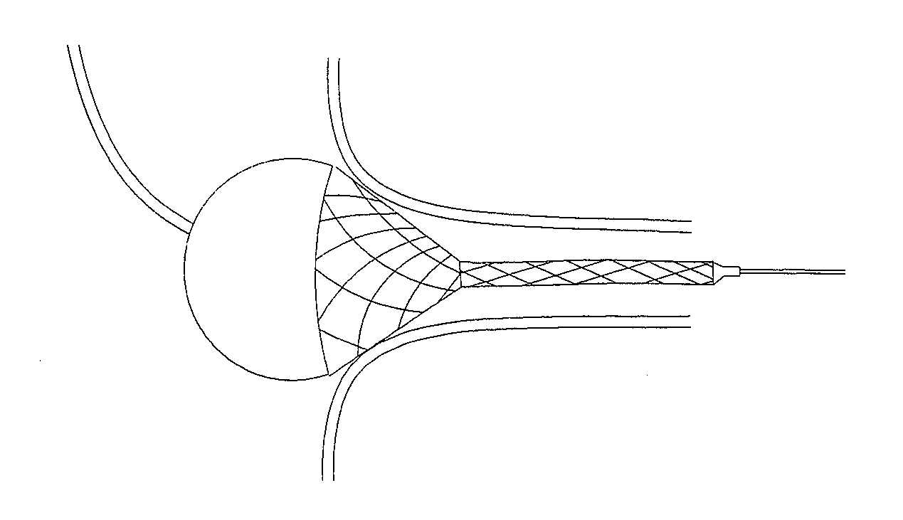
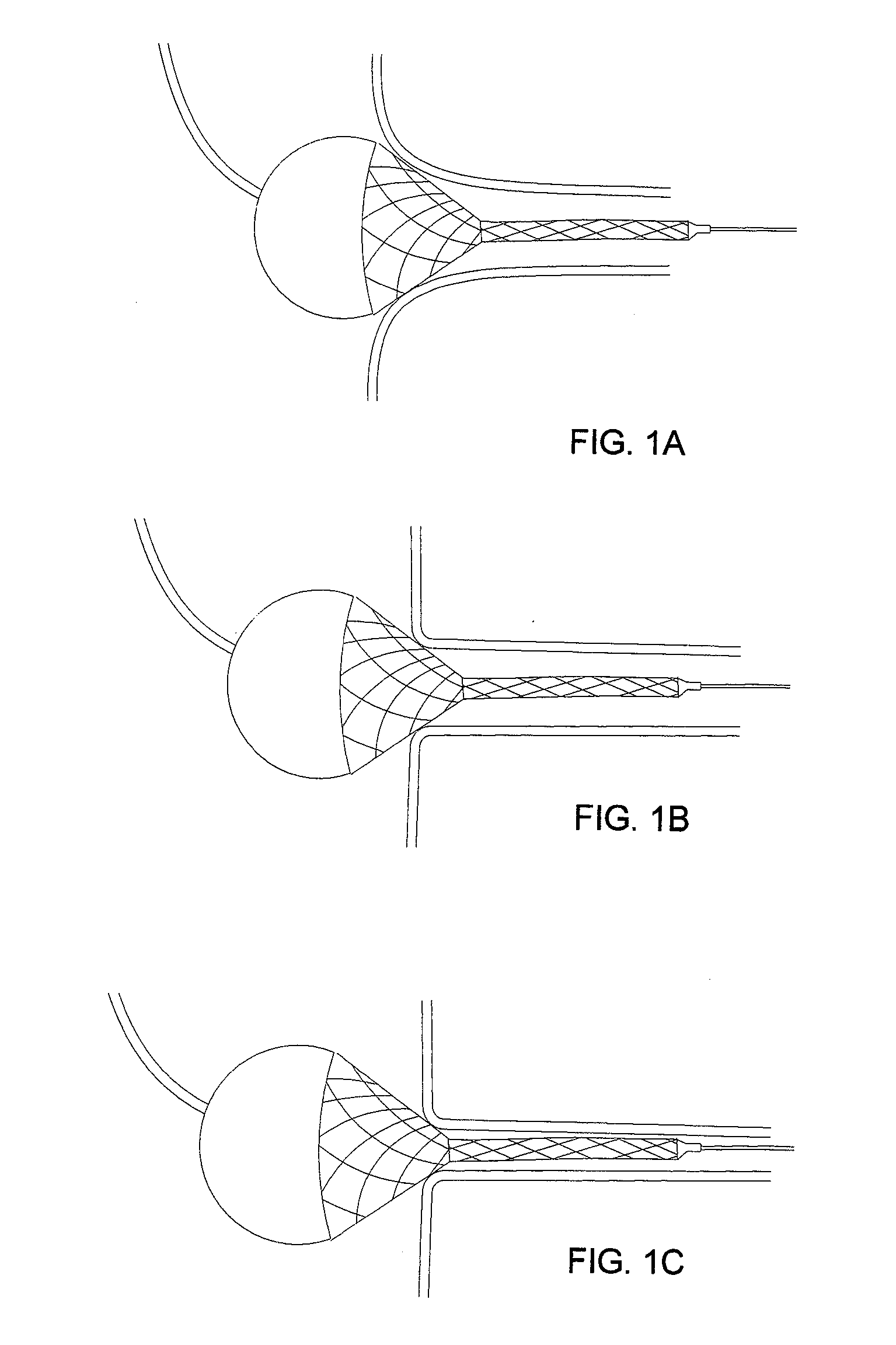
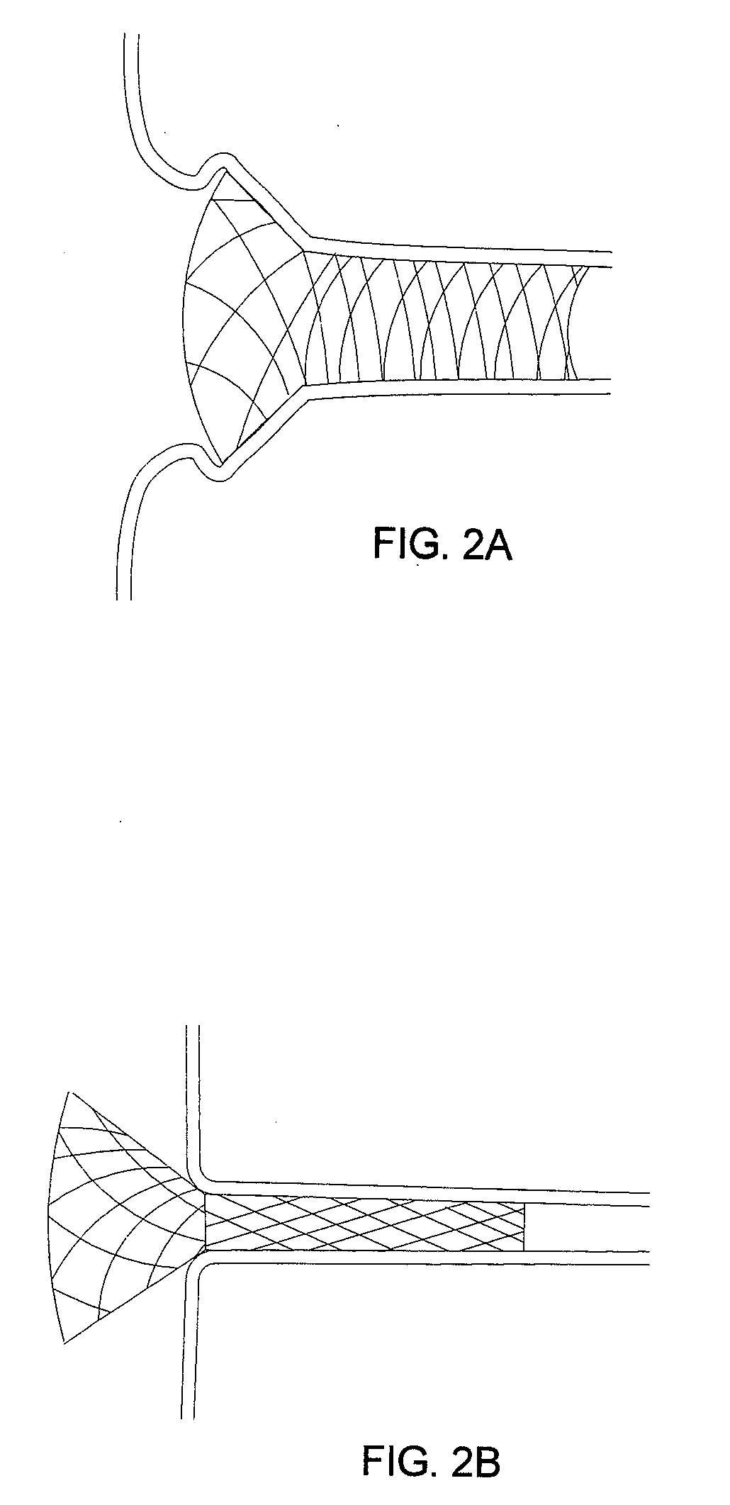
[0069] Turning to the drawings, FIGS. 4-6 show exemplary embodiments of a stent 40 that includes a generally cylindrical tubular member including a proximal or first end 42 and a distal or second end 44 defining a longitudinal axis 46 therebetween. The stent 40 is generally radially expandable from a contracted or delivery condition (not shown), to a flared condition (e.g., as shown in FIGS. 5A, 6A, and 6C), and to an enlarged or filly deployed condition (e.g., as shown in FIGS. 5B, and 6B-6E). For example, the stent 40 may include a first end portion 41 at the first end 42 and a second portion 43 adjacent the first end portion 41, and a plurality of connectors 10 connecting the second portion 43 to the first end portion 41.

[0070] In an exemplary embodiment, the stent 40 may include a plurality of annular bands of cells 47-49 disposed between the proximal and distal ends 42, 44. Each band of cells 47-49 may be defined by a plurality of struts or other elements extending axially alo...


PUM


Abstract

Flared stents are disclosed, and apparatus and methods for delivering such stents into a bifurcation between a main vessel and a branch vessel. The stent includes a first tubular portion a second flaring portion that may be flared radially outwardly to contact the ostium. The stent may include variable mechanical properties along its length. The stent may be delivered using a catheter including proximal and distal ends, the stent overlying first and second balloons on the distal end. During use, the catheter is advanced through an ostium into the branch to place the stent within the branch. The first balloon is expanded to flare the stent to contact a wall of the ostium, thereby causing the stent to migrate partially into the ostium. The second balloon is expanded to filly expand the stent within the ostium and branch.

Description

[0001] This application claims benefit of provisional applications Ser. Nos. 60 / 710,521, filed Aug. 22, 2005, 60 / 727,703, filed Oct. 17, 2005, 60 / 757,600, filed Jan. 9, 2006, 60 / 743,880, filed Mar. 28, 2006, and 60 / 745,177, filed Apr. 19, 2006, the entire disclosures of which are expressly incorporated by reference herein. FIELD OF THE INVENTON [0002] The present invention relates generally to endoluminal prostheses or “stents,” and, more particularly, to flared stents, and to apparatus and methods for delivering such stents into an ostium of a blood vessel or other body lumen. BACKGROUND [0003] Tubular endoprosthesis or “stents” have been suggested for dilating or otherwise treating stenoses, occlusions, and / or other lesions within a patient's vasculature or other body lumens. For example, a self-expanding stent may be maintained on a catheter in a contracted condition, e.g., by an overlying sheath or other constraint, and delivered into a target location, e.g., a stenosis within a...

Claims


Application Information

Patent Timeline
Patent Type & Authority Applications(United States)
IPC IPC(8): A61F2/06A61F2/82
CPCA61F2/91A61F2230/0067A61F2/958A61F2002/30322A61F2002/821A61F2002/91525A61F2002/91533A61F2002/91558A61F2250/0018A61F2250/0026A61F2250/0039A61M25/1002A61F2230/005A61F2230/0054A61F2/915
Inventor KROLIK, JEFFREY A.KIM, ELIOTDREHER, JAMES HOWARD
Owner INCEPT LLC
Learn More