

Method and apparatus for FFT computation
a signal processing and signal processing technology, applied in the field of ifft/fft signal processing method, can solve the problems of high cost in every aspect, and achieve the effect of reducing labor intensity, facilitating the computation of 2n points, and reducing the cost of sta
- Summary
- Abstract
- Description
- Claims
- Application Information
AI Technical Summary
Problems solved by technology
Method used
Image

Examples
first embodiment
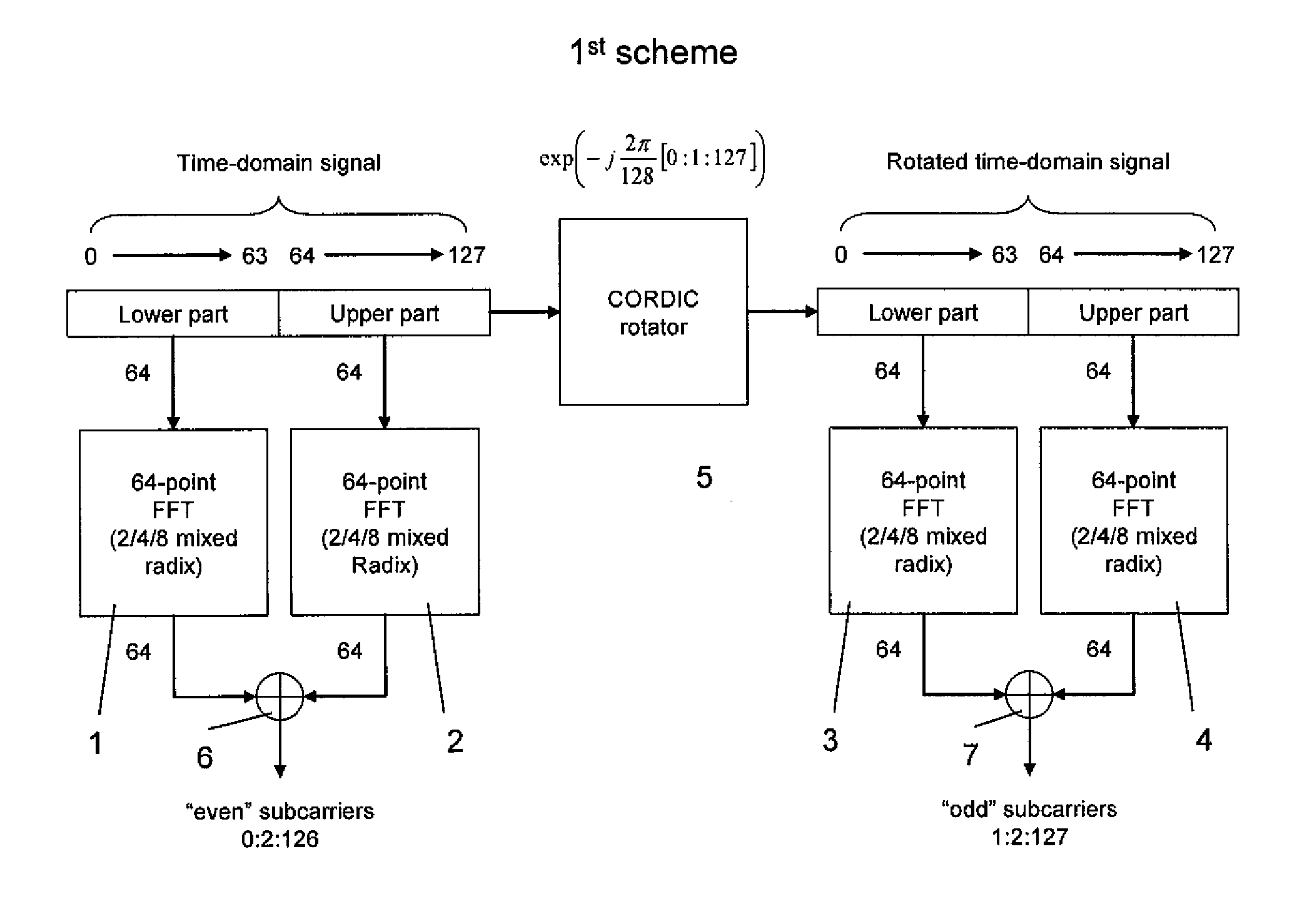
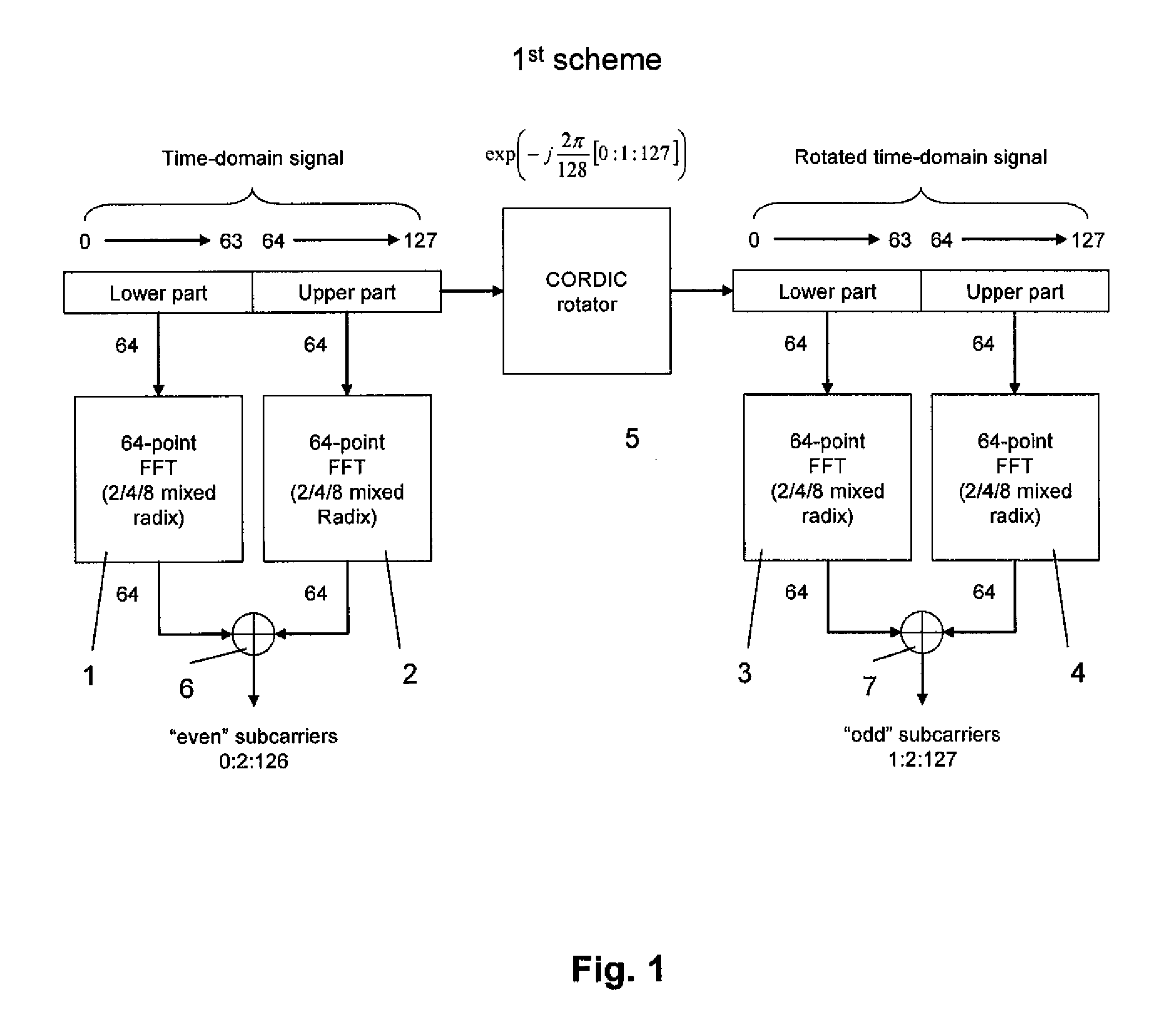
[0018]FIG. 1 shows a block diagram of the signal processor according to the invention. A time domain signal, for example an OFDM baseband signal, consisting for example of N=128 digital samples x(n) is split into a lower part signal xlower(n) and an upper part signal xupper(n) each consisting of N / 2=64 samples. The lower part signal Xlower(n) and the upper part signal xupper(n) are each input to a 64-point FFT signal processor 1, 2 and subjected in parallel (or consuctively) to a 64-point FFT with 2 / 4 / 8 mixed radix. The FFT signal processing results in a lower part frequency domain signal X N 2 lower(k)
and a upper part frequency domain signal XN2upper(k).
These two signals XN2lower(k) and XN2upper(k)
are fed to an adder circuit 6 and added together to form a frequency domain signal comprising the “even” subcarriers 0:2:126 of the OFDM baseband signal.
[0019] At the same time, the lower part signal xlower(n) and the upper part signal xupper(n) are input to a CORDIC (...
second embodiment
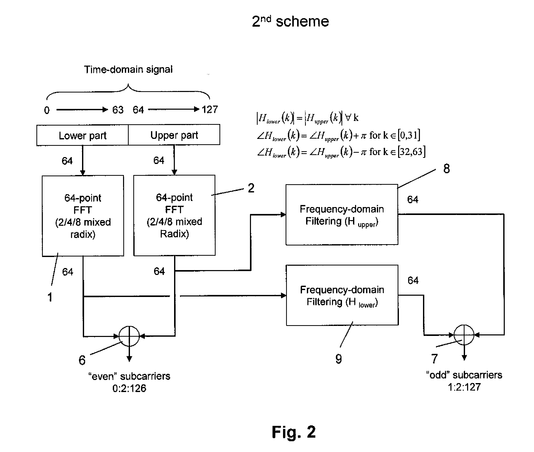
[0020] According to the invention shown in FIG. 2, a time domain signal, for example an OFDM baseband signal, consisting for example of N=128 digital samples x(n) is split into a lower part signal xlower(n) and an upper part signal xupper(n) each consisting of N / 2=64 samples. The lower part signal xlower(n) and the upper part signal xupper(n) are each input to a 64-point FFT signal processor 1, 2 and subjected in parallel (or consecutively) to a 64-point FFT with 2 / 4 / 8 mixed radix. This results in a lower part frequency domain signal X N 2 lower(k)
and a upper part frequency domain signal XN2upper(k).
These two signals XN2lower(k) and XN2upper(k)
are fed to an adder 6 and added together to form a frequency domain signal comprising the “even” subcarriers 0:2:126 of the OFDM baseband signal.
[0021] At the same time, the two signals XN2lower(k) and XN2upper(k)
are are individually fed to filter circuits 8, 9 and subjected to a frequency domain filtering Hlower an...
third embodiment
[0023] According to the in invention as depicted in FIG. 3, a time domain signal, for example an OFDM baseband signal, consisting for example of N=128 digital samples x(n) is splitted into a lower part signal xlower(n) and an upper part signal xupper(n) each consisting of N / 2=64 samples. In a first branch, the lower part signal xlower(n) and the upper part signal xupper(n) are added by means of an adder circuit 10, input to a 64-point FFT signal processor 1 and subjected to a 64-point FFT with 2 / 4 / 8 mixed radix. This results in a frequency domain signal comprising the “even” subcarriers 0:2:126 of the OFDM baseband signal.
[0024] In a second branch, the upper signal part xuppe(n) is subtracted from the lower part signal xlower(n) by means of an adder 11 (substactor). The resulting singal is input to a 64-point FFT signal processor 2 and subjected to a 64-point FFT with 2 / 4 / 8 mixed radix. This results in a frequency domain signal which is input to a filter circuit 9 and further subjec...
PUM
 Abstract
Description
Claims
Application Information