Apparatus for peeling adhesive tape

a technology of adhesive tape and apparatus, which is applied in the direction of transportation and packaging, solid-state devices, semiconductor devices, etc., can solve the problems of circuit pattern breaking, and achieve the effect of efficiently peeling adhesive tapes, and efficient peeling of adhesive tapes

Inactive Publication Date: 2007-04-05
LINTEC CORP
View PDF5 Cites 24 Cited by
  • Summary
  • Abstract
  • Description
  • Claims
  • Application Information

AI Technical Summary

Benefits of technology

[0023] According to the invention set forth in claim 1, as the peeling tape adhered over the entire surface of the adhesive tape is heated together with the adhesive tape, the fragmented adhesive tapes stick to the peeling tape, so that the adhesive tapes are peeled from the plate-shaped member together with the peeling tape, and the peeled adhesive tapes and peeling tape are collected, thereby making it possible to readily peel the fragmented adhesive tapes from the plate-shaped member. A sequence of these steps are performed by the peeling apparatus which comprises the peeling tape supplying means, peeling tape adhering means, heating means, tape peeling means, and collecting means, thereby making it possible to efficiently carry out the operation for peeling the adhesive tapes.
[0024] According to the invention set forth in claim 2, since a continuous sheet-shaped tape is used as the peeling tape, the fragmented adhesive tapes can be successively adhered to the continuous sheet-shaped member to efficiently peel the adhesive tapes from the plate-shaped member for collecting. Also, by implementing the peeling tape adhering means and tape peeling means by a common roller unit, the peeling apparatus can be simplified in structure and reduced in cost.
[0025] According to the invention set forth in claim 3, a tape previously cut in conformity to the surface shape of the plate-shaped member is used as the peeling tape. By holding and pulling a second adhesive tape adhered to an end of the peeling tape by a peeling head, the adhesive tape can be readily and efficiently peeled from the plate-shaped member together with the peeling tape.
[0026] According to the invention set forth in claim 4, since a tape comprising an adhesive layer deposited on a heat-shrinkable base is used as the adhesive tape, the heat-shrinkable base shrinks as the adhesive tape is heated, causing the respective fragmented adhesive tapes to curve and therefore be in contact with the plate-shaped member in a reduced area. Thus, each adhesive tape more readily peels from the plate-shaped member, and they readily stick to the peeling tape and are peeled from the plate-shaped member and collected together with the peeling tape.
[0027] According to the invention set forth in claim 5, as ultraviolet rays are irradiated to an adhesive tape having an adhesive layer made of an ultraviolet curable adhesive by the ultraviolet ray irradiating means, the adhesive layer of the adhesive tape is cured to weaken the adhesive strength of the adhesive tape, causing each of the fragmented adhesive tapes to more readily peel from the plate-shaped member. They are readily peeled from the plate-shaped member together with the peeling tape for collect.
[0028] According to the invention set forth in claim 6, by cooling the heated peeling tape and adhesive tape, the operation time can be reduced to further increase the efficiency.

Problems solved by technology

Incidentally, grinding debris can be produced during the grinding of a wafer, and if the grinding debris come in contact with a circuit pattern, the circuit pattern can be broken.

Method used


Image

  • Apparatus for peeling adhesive tape
  • Apparatus for peeling adhesive tape
  • Apparatus for peeling adhesive tape

Examples


second embodiment

[0144] Next, the present invention will be described with reference to FIG. 17. FIG. 17 is a top plan view of a peeling apparatus according to this embodiment.

first embodiment

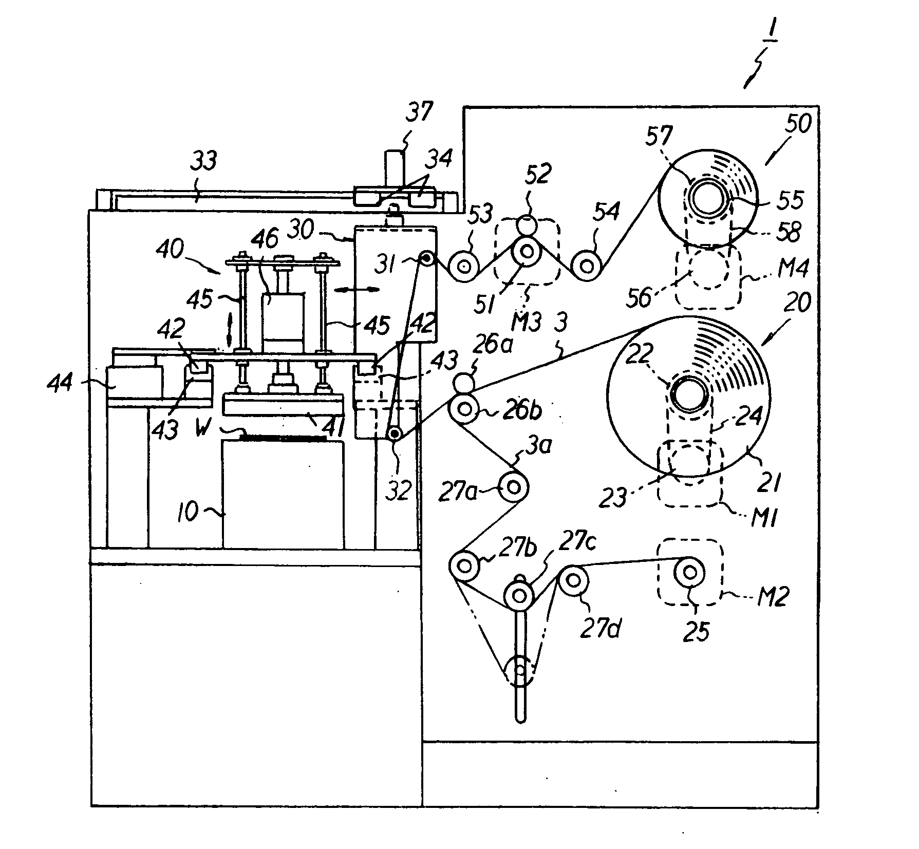
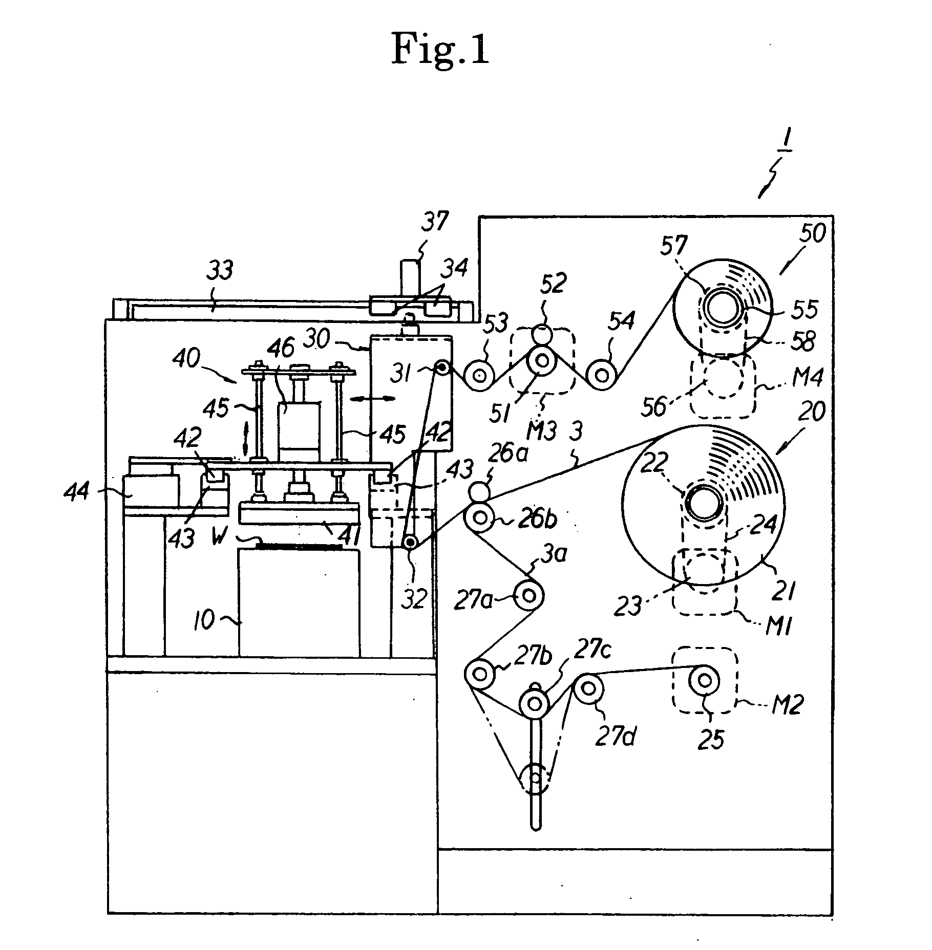
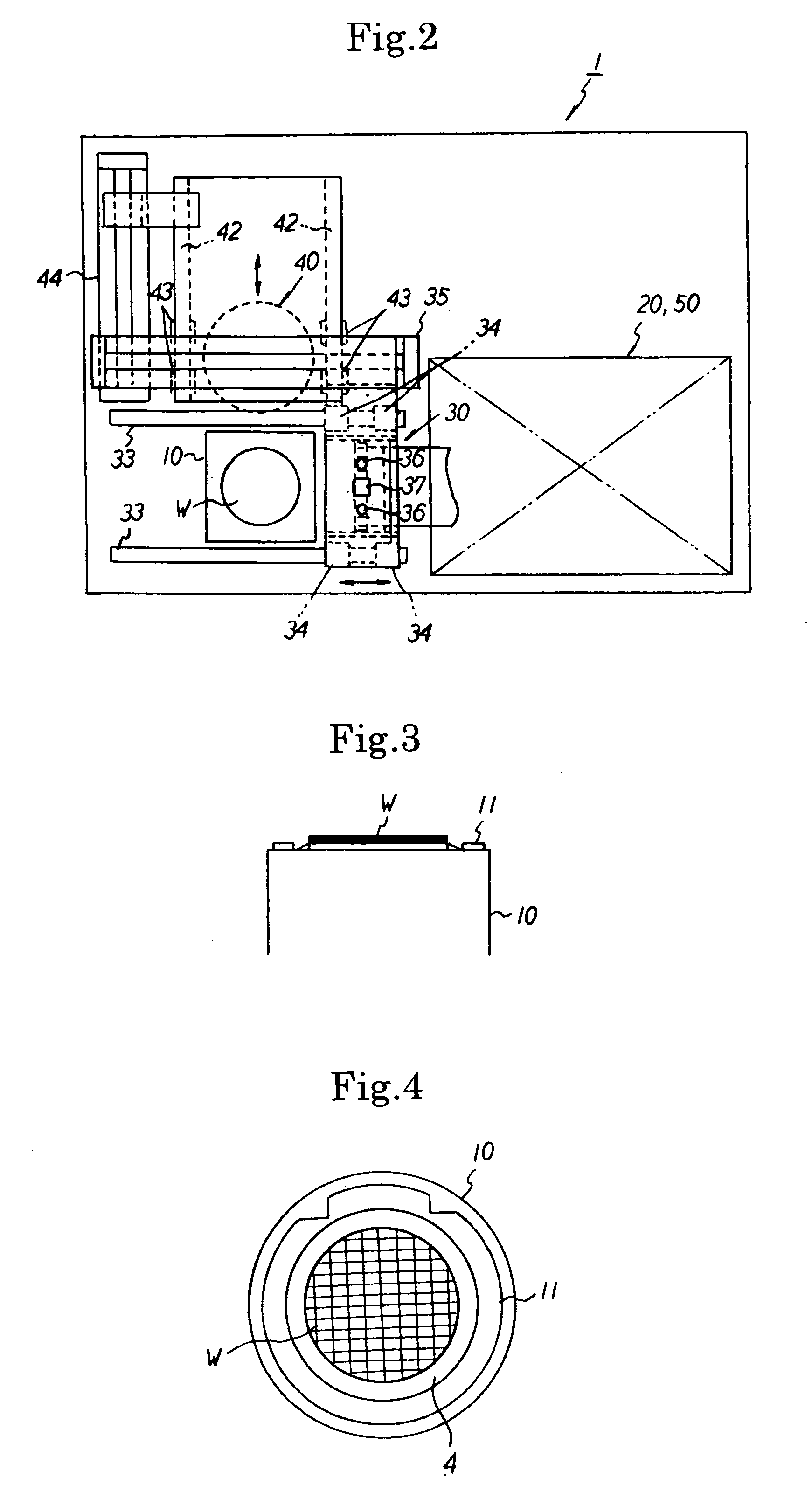
[0145] The peeling apparatus 1′ according to this embodiment additionally comprises a frame chucking unit 70 for automatically bringing and removing a wafer (integrated with the ring frame 11) into and from a frame cassette 71; and a UV irradiation unit 80 for irradiating ultraviolet rays (UV) to a surface protection tape 2 (2a) which has an adhesive layer 2B, shown in FIG. 2B, made of an ultraviolet curable adhesive, and the remaining configuration is the same as that of the peeling apparatus 1 i.e., comprises the suction table 10, peeling tape unit 20, adhesion / peeling roller unit 30, heating / cooling unit 40, and tape wind unit 50.

[0146] The frame chucking unit 70 extracts one of a plurality of wafers W stored in the frame cassette 71 which are arranged with a proper space defined therebetween in the vertical direction, peels the surface protection tape 2 (2a) from the surface of the extracted wafer W, and places the wafer W, from which the surface protection tape 2 (2a) has been...


PUM

PropertyMeasurementUnit
temperatureaaaaaaaaaa
sizeaaaaaaaaaa
shapeaaaaaaaaaa

Abstract

An apparatus for peeling an adhesive tape is provided for enabling fragmented adhesive tapes to be readily and efficiently peeled from a plate-shaped member. The apparatus for peeling a surface protection tape (adhesive tape) 2a adhered on the surface of a wafer (plate-shaped member) W and fragmented into chip-size pieces from the wafer W comprises peeling tape supplying means 20 for feeding a peeling tape 3 to the wafer W set on a suction table 10; peeling tape adhering means for adhering the peeling tape 3 fed out by the peeling tape supplying means 20 over the entire surface of the surface protection tape 2a adhered on the surface of the wafer W; heating means for heating the peeling tape adhered over the entire surface of the adhesive tape by the peeling tape adhering means together with the adhesive tape; tape peeling means for peeling the adhesive tape sticking to the peeling tape through the heating by the heating means from the plate-shaped.

Description

TECHNICAL FIELD [0001] The present invention relates to an apparatus for peeling an adhesive tape from a plate-shaped member, such as a surface protection tape adhered on the surface of the plate-shaped member of a semiconductor wafer or the like which has been fragmented into chip-size pieces. BACKGROUND ART [0002] In a semiconductor chip manufacturing process in electronic industries and optical industries, after predetermined circuit patterns have been formed on the surface of a semiconductor wafer (hereinafter simply called the “wafer”), the rear surface of the wafer is ground in order to uniformly reduce the thickness of the wafer or in order to remove an oxide film generated during the formation of the circuits, followed by dicing (fragment) the wafer into individual circuits to manufacture semiconductor chips. [0003] Incidentally, grinding debris can be produced during the grinding of a wafer, and if the grinding debris come in contact with a circuit pattern, the circuit patt...

Claims


Application Information

Patent Timeline
Patent Type & Authority Applications(United States)
IPC IPC(8): B29C63/00B65H37/00B65H41/00H01L21/00H01L21/68H01L21/78
CPCB29C63/0013B65H37/002B65H2701/192H01L21/67132Y10T156/19H01L2221/6834H01L2221/68395Y10T156/1911H01L21/6835
Inventor AKECHI, TAKESHI
Owner LINTEC CORP
Why Eureka
Try Eureka