Welding teaching point correction system and calibration method

a correction system and teaching technology, applied in process control, process and machine control, process control, etc., can solve the problems of inability to correct off-line teaching data, sometimes shifted welding position, and high equipment cost, so as to increase the accuracy of correction of teaching program.

Inactive Publication Date: 2007-04-05
NACHI-FUJIKOSHI
View PDF2 Cites 55 Cited by
  • Summary
  • Abstract
  • Description
  • Claims
  • Application Information

AI Technical Summary

Benefits of technology

[0045] Thereby, even if the direction of the image and the distance from the center of the imaging area of the image to the specific point are unknown, the direction of the image and the distance from the center of the imaging area of

Problems solved by technology

However, in the case where a program created by the off-line teaching system is uploaded to and used in an actual robot after the installation of the equipment, a welding position is sometimes shifted from an expected position owing to installation errors of the robot and the jig thereof, the individual difference of the robot, the dimension error of the workpiece, deflection caused by the gravity, and the like.
However, the disclosure of JP 3191563B has a problem that the off-line teaching data can be corrected only in data component of one direction.
Moreover, because it is necessary to mark on the front-back both surfaces at a welding point of a workpiece and to install two cameras for imaging the respective marks, the disclosure of JP 3191563B has another problem that the costs of the equipment becomes high and the preparation thereof is complicated and needs a lot of trouble.
Moreover, because in the disclosure of JP 2005-138223A a camera is

Method used


Image

  • Welding teaching point correction system and calibration method
  • Welding teaching point correction system and calibration method
  • Welding teaching point correction system and calibration method

Examples


Embodiment Construction

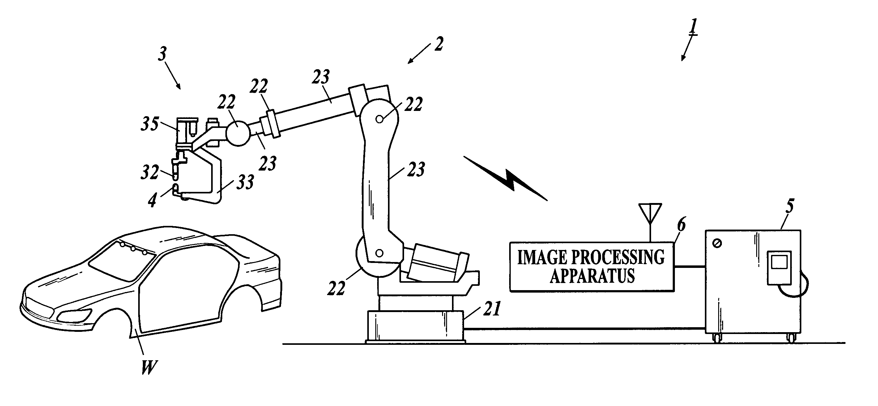
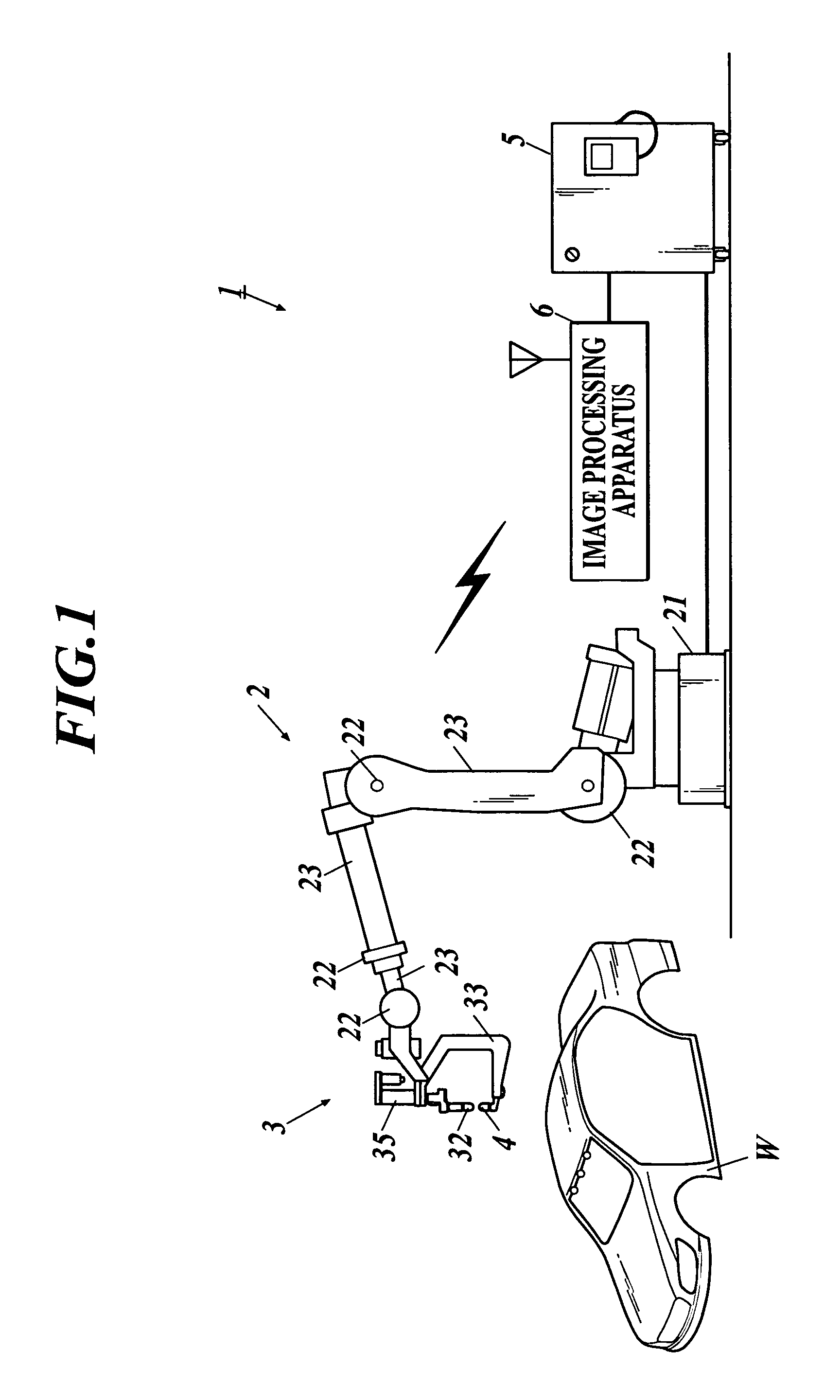
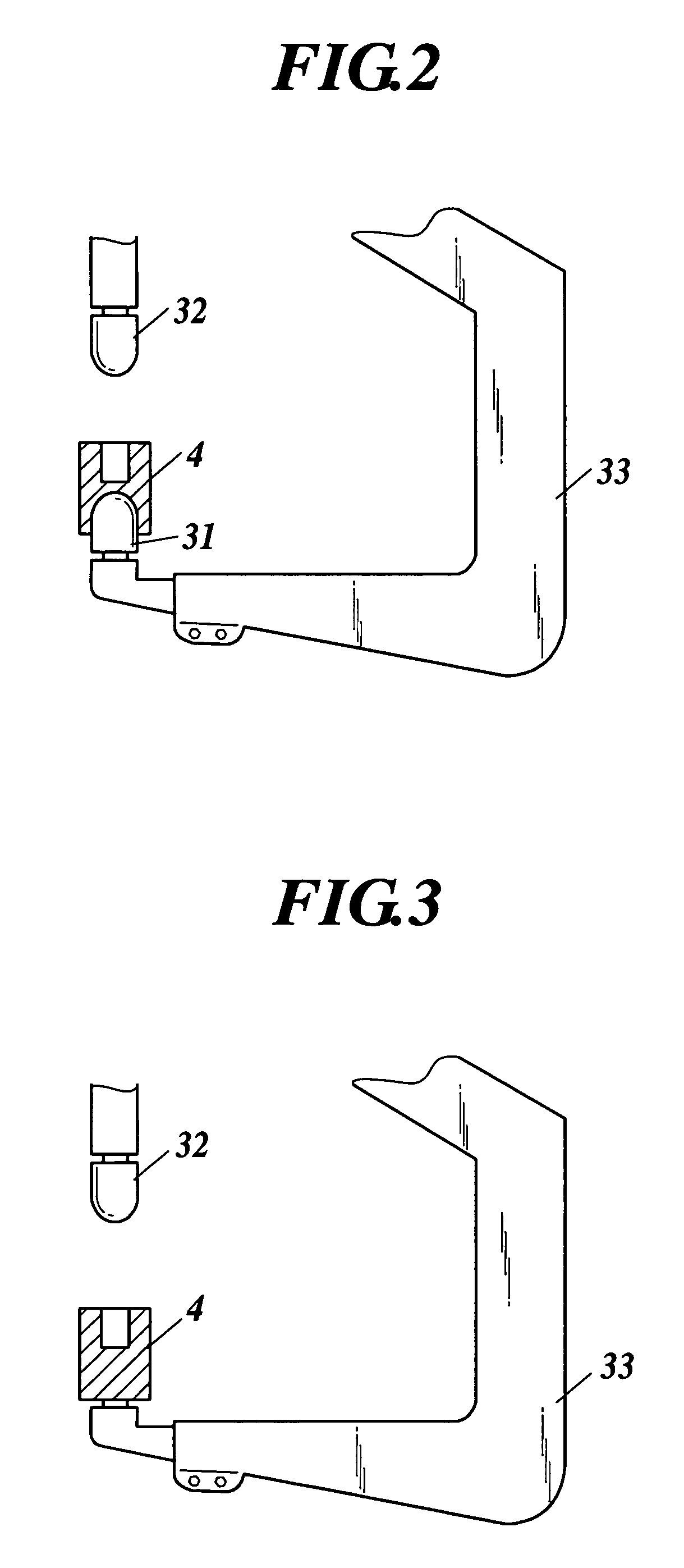
[0058] In the following, the best embodiment of a welding teaching point correction system and a calibration method are described in detail with reference to the attached drawings. In addition, the direction perpendicular to the axial direction of a welding tip is supposed to an X direction, the direction perpendicular to the axial direction of the welding tip and perpendicular to the X direction is supposed to a Y direction, and the direction along the axial direction of the welding tip is supposed to a Z direction at the time of the correction of an welding teaching point.

[0059] As shown in FIG. 1, a welding teaching point correction system 1 is equipped with a multi-axis robot 2 having a plurality of joints and arms, a spot welding gun 3 provided at the tip of the robot 2, a camera 4 as an imaging apparatus to image a welding point of a workpiece W to which spot welding is performed by the spot welding gun 3, a control apparatus 5 to perform the operation control of the robot 2,...


PUM

PropertyMeasurementUnit
Sizeaaaaaaaaaa
Distanceaaaaaaaaaa

Abstract

Disclosed is a welding teaching point correction system, including: a robot; a spot welding gun comprising two welding tips provided to be opposed to each other; an imaging apparatus to image a welding point of a workpiece, the imaging apparatus being provided detachably to or exchangeably with at least one of the two welding tips; an operation control unit to control the robot and the spot welding gun in accordance with an teaching program to teach welding operation to the robot and the spot welding gun; an image processing unit to acquire positional information of the welding point of the workpiece in the image; and a program correction unit to correct an teaching point for the robot in the teaching program in a plurality of directions based on the positional information of the welding point of the workpiece in the image acquired by the image processing unit.

Description

BACKGROUND OF THE INVENTION [0001] 1. Field of the Invention [0002] The present invention relates to a welding teaching point correction system and a calibration method. [0003] 2. Description of Related Art [0004] In a process such as a spot welding line of an automotive body where many spot welding robots are used, a technique of preparing an operation program of the robots beforehand has been employed for the purpose of the reduction of work man-hour and the shortening of working hours at starting up the equipment. As the method of previously preparing an operation program of a spot welding robot before the installation of the equipment, an off-line teaching system has been used, which creates a program by simulating robot operations on a computer based on the information pertaining to the mechanisms and the shapes of the robot and the spot welding gun thereof, the shape of a workpiece (material to be welded), a relative positional relation between the robot and the workpiece, nec...

Claims


Application Information

Patent Timeline
IPC IPC(8): B23K11/10
CPCB23K11/253B25J9/1692B25J9/1697G05B19/4083G05B2219/36048G05B2219/36404G05B2219/39056G05B2219/39057G05B2219/40003G05B2219/45104
Inventor KUNISAKI, AKIRATAKATA, HISANORI
Owner NACHI-FUJIKOSHI
Why Eureka
Try Eureka