Method of sealing a free edge of a composite material

a free edge and composite material technology, applied in the field of materials technology, can solve the problems of easy fracture of tensile stress, high degree of brittleness of ceramic materials, and high degree of brittleness, and achieve the failure of not only the cmc material but also a component formed from the cmc material

Inactive Publication Date: 2007-04-05
SIEMENS ENERGY INC
View PDF13 Cites 41 Cited by
  • Summary
  • Abstract
  • Description
  • Claims
  • Application Information

AI Technical Summary

Problems solved by technology

However, ceramic materials are easily fractured by tensile stresses and exhibit a high degree of brittleness.
A fundamental problem with this type of material system is its susceptibility to free edge stresses under thermal and mechanical loads.
This may result in delaminating

Method used


Image

  • Method of sealing a free edge of a composite material
  • Method of sealing a free edge of a composite material

Examples


Embodiment Construction

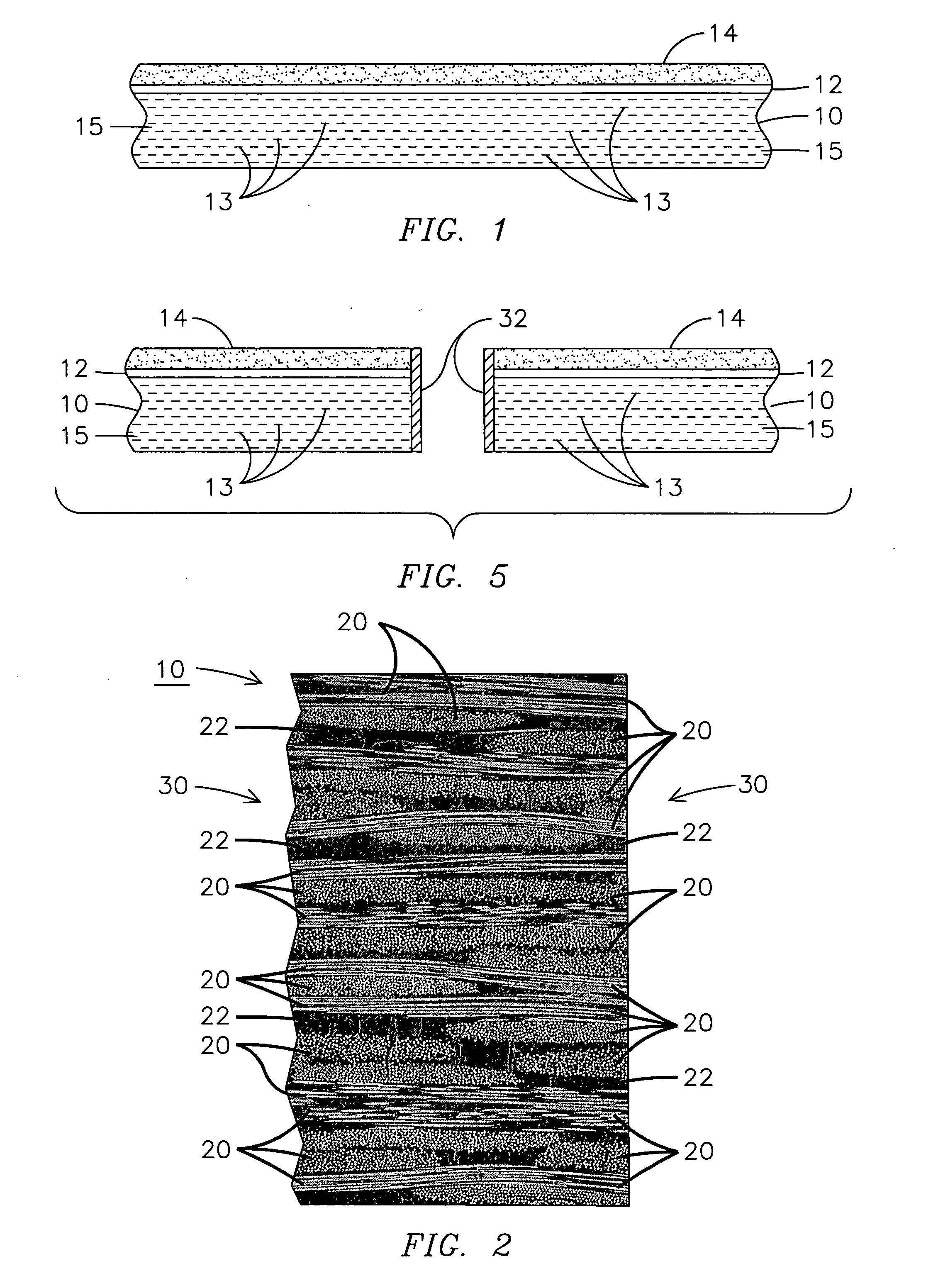
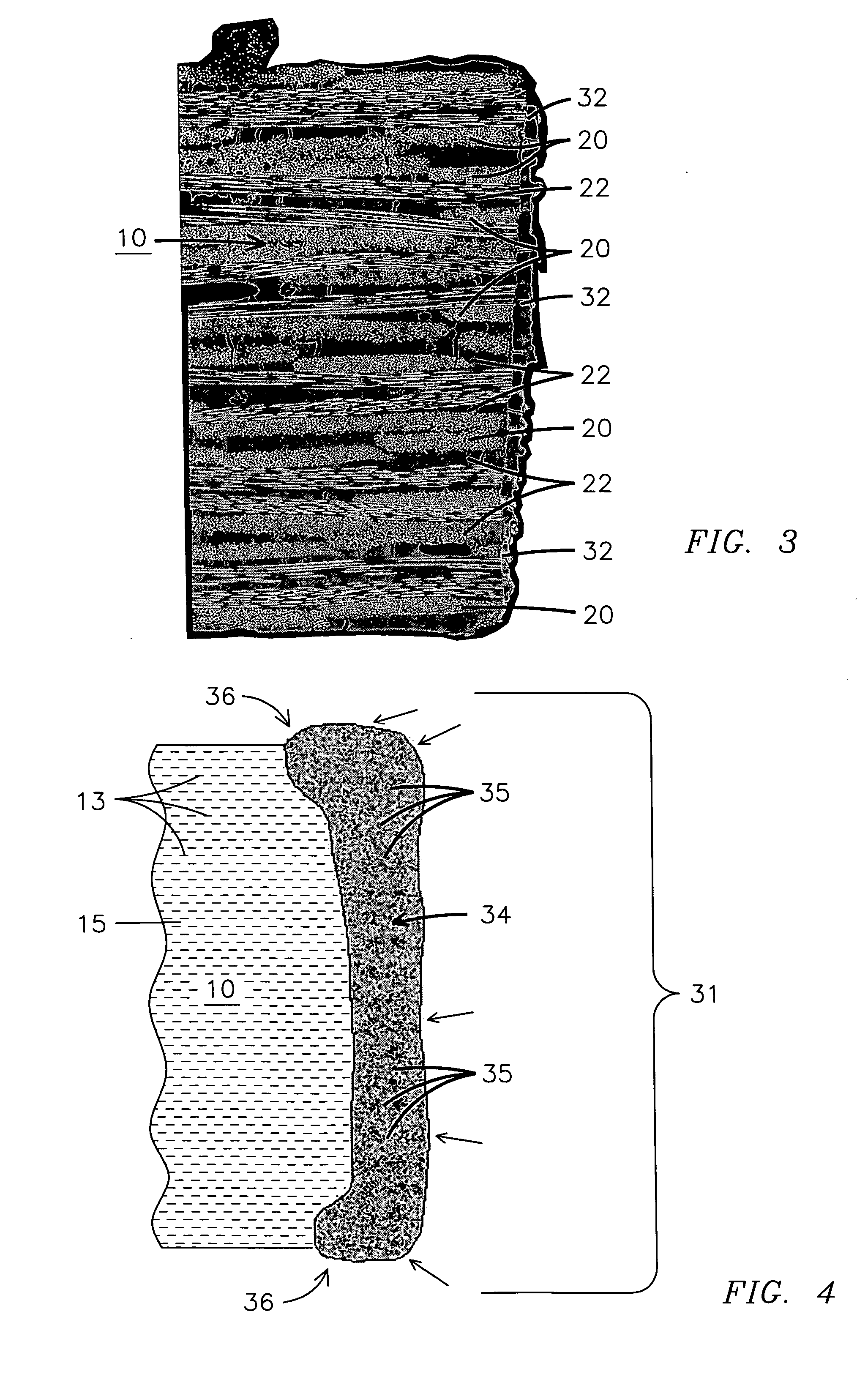
[0010]FIG. 1 illustrates a partial cross-sectional view of a ceramic matrix composite (CMC) material 10 having an adhesive 12 and a protective coating 14 deposited thereon. An exemplary CMC material 10 may have a plurality of layers of ceramic fibers 13 disposed with a ceramic matrix material 15. CMC material 10 may be used to cover or form various components as recognized by those skilled in the art. Another exemplary CMC material 10, shown in FIG. 2, may have a plurality of fabric laminate layers 20 interposed among a plurality of matrix material layers 22 to form a 2-dimensional composite layer CMC material 10. Layers 20 may be woven or wound so that fibers are in two directions and essentially in one plane. For typical 2-dimensional fiber structures, the two principle fiber directions are typically, but not necessarily, orthogonal as appreciated by those skilled in the art.

[0011] Laminate layers 20 may be, for example, woven fabric such as oxide based ceramic fibers selected fr...


PUM

PropertyMeasurementUnit
Temperatureaaaaaaaaaa
Thicknessaaaaaaaaaa
Forceaaaaaaaaaa

Abstract

A method of coating an edge surface (30) of an anisotropic ceramic matrix composite material (10) for use in a high temperature environment is disclosed where the edge surface (30) has exposed reinforced fiber layers (20). A laser beam may be used to melt a portion of the ceramic matrix composite material (10) on the edge surface (30) forming a melt layer. The melt layer is retained proximate the edge surface and the laser beam is controlled to form an isotropic protective coating (32, 34) on a portion of the edge surface (30). A method may be used to form a component for use in a high temperature environment that includes directing a laser beam toward a ceramic matrix composite material (10), controlling the laser beam to melt a portion of the ceramic matrix composite material (10) and forming a homogeneous protective coating (32, 34) from a melt layer that exerts compression on at least a portion of the ceramic matrix composite material (10) when the melt layer is cooled. A powder material (35) may be added to a surface of the ceramic matrix composite material (10) selected to melt with the ceramic matrix composite material (10) to improve the wear resistance or hardness of the isotropic protective coating (32, 34).

Description

FIELD OF THE INVENTION [0001] This invention relates in general to materials technology and more particularly to a method of sealing an edge of exposed material such as a 2-dimensional laminated composite structure. BACKGROUND OF THE INVENTION [0002] Ceramic materials generally have excellent hardness, heat resistance, abrasion resistance, and corrosion resistance and are desirable for high temperature machine applications such as gas turbines and the like. However, ceramic materials are easily fractured by tensile stresses and exhibit a high degree of brittleness. To improve upon the fracture toughness of a ceramic material, it is known to provide a ceramic matrix composite (CMC) material wherein a plurality of inorganic fibers are disposed in a matrix of ceramic material. [0003] A CMC material may be formed by impregnating a preform of fiber containing fabric material with ceramic material powder using a known wet method such as slip casting or slurry infiltration. Alternate metho...

Claims


Application Information

Patent Timeline
IPC IPC(8): B29C45/14D04H5/00D04H1/00B05D3/02D04H13/00D04H3/00
CPCC04B41/0036C04B41/009C04B41/87C04B41/4523C04B41/4572C04B41/5027C04B35/803Y10T428/249924
Inventor MARINI, BONNIE D.MERRILL, GARY B.LANE, JAY E.
Owner SIEMENS ENERGY INC
Why Eureka
Try Eureka