Variable gain amplifier

a gain amplifier and variable gain technology, applied in the direction of amplifiers with semiconductor devices/discharge tubes, differential amplifiers, amplifiers, etc., can solve the problems of not being taken into consideration, increasing the number of taps of the amplifier to a level where discrete intervals could be ignored, and being too discrete without proper consideration of the continuity of variable gain. , to achieve the effect of low noise level

Inactive Publication Date: 2007-04-05
ABLIC INC
View PDF4 Cites 6 Cited by
  • Summary
  • Abstract
  • Description
  • Claims
  • Application Information

AI Technical Summary

Benefits of technology

[0011] A representative effect of the present invention by the above means is to be able...

Problems solved by technology

In this circuit, however, the combination of mutual conductance amplifiers in relation to control voltage, that is, the setting of variable gain amplifiers, is rather too discrete without proper consideration paid for the continuity of variable gain in relation to control voltage.
On the other hand, increasing the number of taps of the amplifier to a level wher...

Method used


Image

  • Variable gain amplifier
  • Variable gain amplifier
  • Variable gain amplifier

Examples


first embodiment

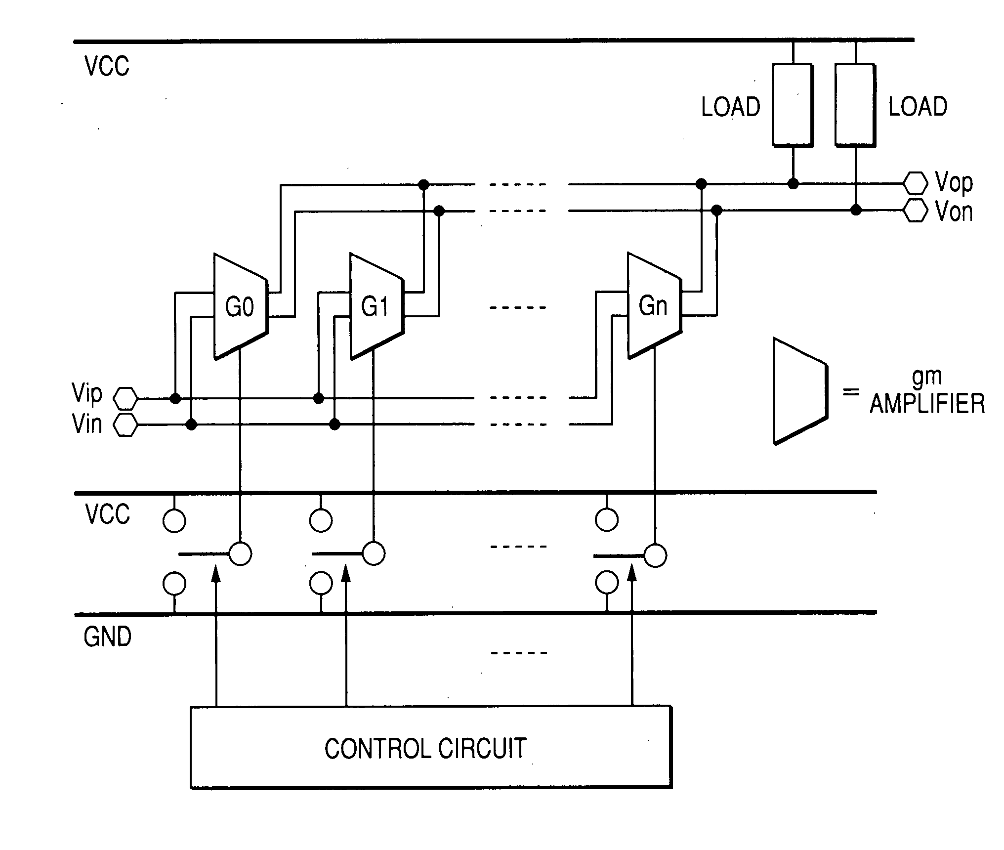
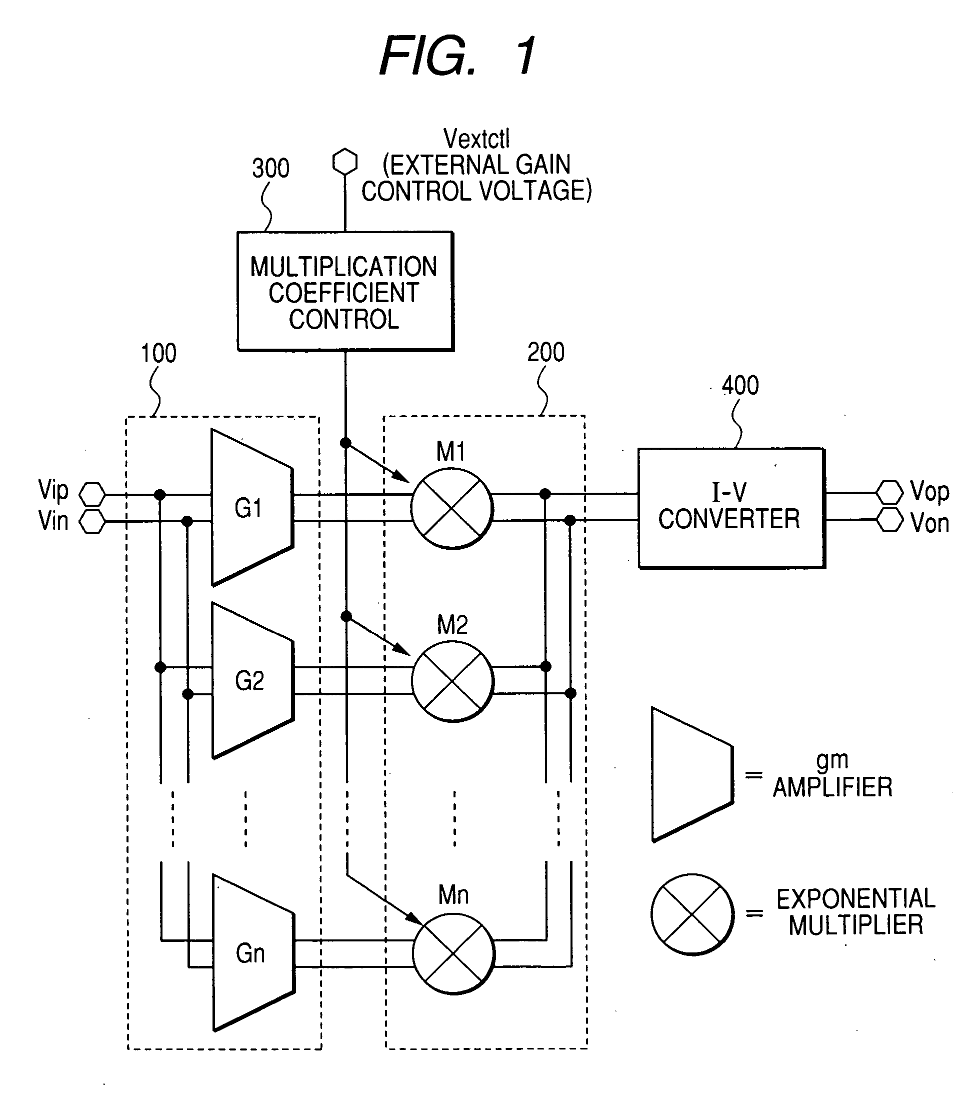
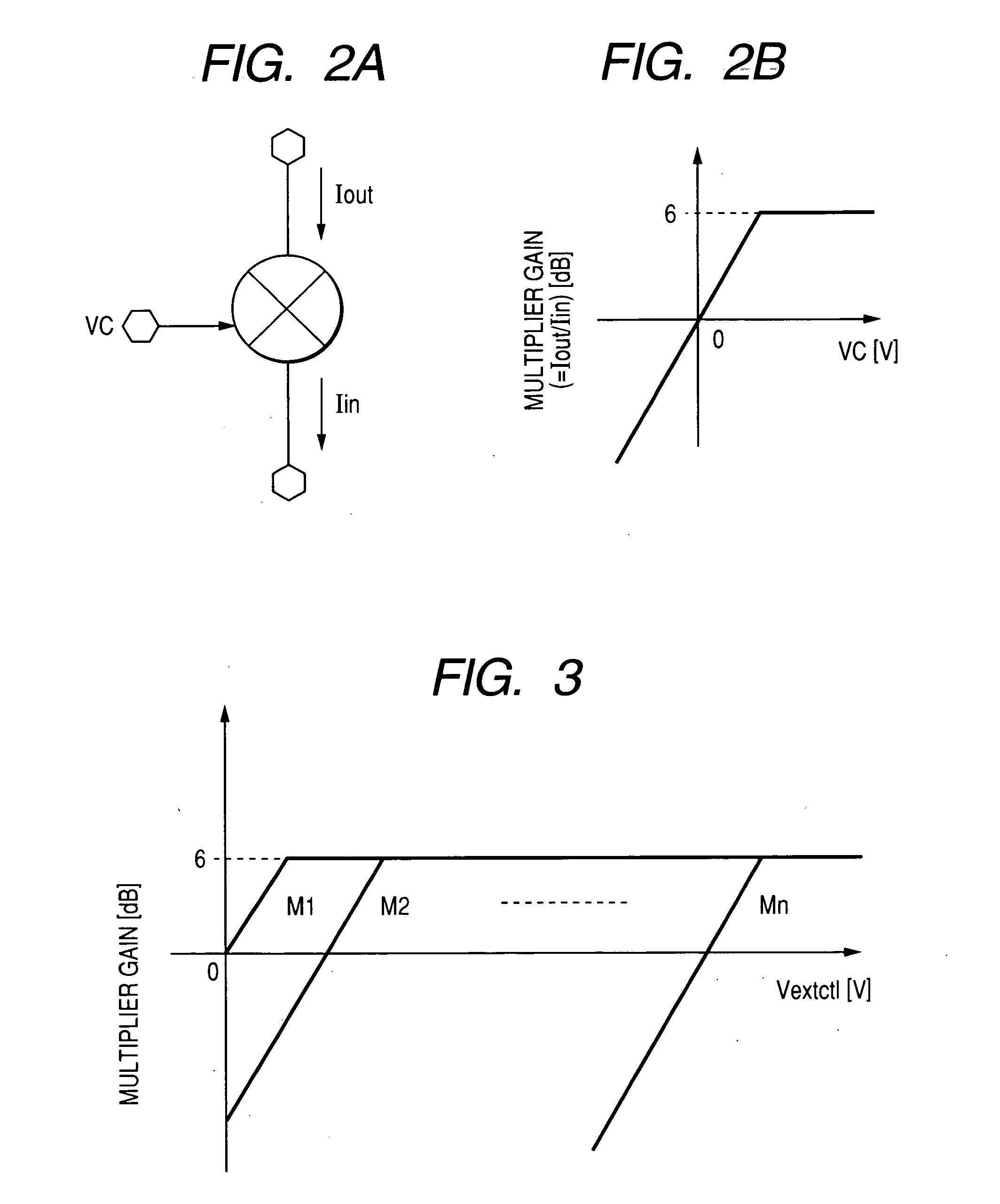
[0025]FIG. 1 represents a first embodiment of the variable gain amplifier according to the present invention. This variable gain amplifier includes the gm amplifier section 100 having a plurality of gm amplifiers G1 to Gn connected in parallel with the differential inputs Vip and Vin, the multiplier section 200 having the exponential multipliers M1 to Mn to conduct exponential multiplication according to respective output currents from the gm amplifiers G1 to Gn, the multiplication coefficient control section 300 to control the multiplication coefficient for the respective exponential multipliers M1 to Mn in accordance with the external gain control voltage Vextctl, and the I-V converter section 400 to aggregate the output currents from the respective exponential multipliers M1 to Mn for conversion to differential voltage outputs Vop and Von. In the above operation, the conductances of the gm amplifiers M1 to Mn are set so that the current amplification ratios can take the values of...


PUM


Abstract

A variable gain amplifier of such configuration that can yield continuously and log-linearly variable gains in relation to control voltage and, at the same time, that does not use an attenuator, an element which otherwise would entail cause of increased noise. The amplifier includes a plurality of gm amplifiers connected in parallel with input signal, exponential multipliers connected respectively to the gm amplifiers, a control section to vary the multiplication coefficient of the exponential multipliers according to the external gain control signal, and an I-V converter circuit to aggregate current output after multiplication and convert the aggregated current output to voltage. A continuously variable gain characteristic can be obtained without the use of an attenuator but by varying multiplication coefficient according to control voltage.

Description

CLAIM OF PRIORITY [0001] The present application claims priority from Japanese application JP 2005-285876 filed on Sep. 30, 2005, the content of which is hereby incorporated by reference into this application. FIELD OF THE INVENTION [0002] This invention relates to a variable gain amplifier and, in particular, to a variable gain amplifier most suitably used for variable gain control of a preamplifier for an ultrasonic diagnostic system. BACKGROUND OF THE INVENTION [0003] JP 1999-177357 A contains a description concerning a variable gain amplifier using MOS. As shown in FIG. 8 (FIG. 1 in the patent document), it is an example of a variable gain amplifier which can realize a predetermined gain by combining an on-and-off of mutual conductance provided individually with a programmable control. [0004] The Data Sheet AD8332 of Analog Devices, Inc. describes a variable gain amplifier suitable for an ultrasonic diagnostic system. Particularly, as shown in FIG. 9 (FIG. 60 in the document), i...

Claims


Application Information

Patent Timeline
IPC IPC(8): H03F3/45
CPCH03F1/26H03F3/45085H03F3/45475H03F3/72H03F2200/372H03F2203/45066H03F2203/45138H03F2203/45288H03F2203/45352H03F2203/45366H03F2203/45561H03F2203/7236H03G1/007H03G7/001
Inventor YOSHIZAWA, HIROYASUHANAZAWA, SATOSHI
Owner ABLIC INC
Why Eureka
Try Eureka