Liquid ejection apparatus and control method for liquid ejection apparatus

Inactive Publication Date: 2007-04-05
FUJIFILM CORP
View PDF6 Cites 13 Cited by
  • Summary
  • Abstract
  • Description
  • Claims
  • Application Information

AI Technical Summary

Benefits of technology

[0014] The present invention has been contrived in view of the foregoing circumstances, an object thereof being to provide a liquid ejection apparatus and a control method for a liquid ejection apparatus, whereby the evaporated volume of liquid at the free surface in the nozzle can be reduced, while also suppressing the consumption of the liquid due to purging, and the like.
[0016] According to this aspect of the present invention, in cases where the liquid is to be ejected from the nozzle, according to requirements, the viscosity of the liquid in the vicinity of the free surface in the nozzle is restored by the vibrating action, whereupon the liquid ejection is performed, and in cases where the liquid is not to be ejected from the nozzle, the frequency of the vibrating action is restricted. Therefore, the evaporation volume at the free surface of the liquid in the nozzle is suppressed, and hence the frequency of purging (dummy ejection) is lowered, the liquid volume required for each purging operation is reduced, and the consumption of the liquid can be restricted. Moreover, even if the frequency of purging or suctioning is reduced, the viscosity at the free surface of the liquid can still be restored over a long period of time, and hence the intervals between purging operations and suctioning operations can be made very long indeed. Therefore, productivity in printing onto a recording medium is improved. Furthermore, the number of vibrating actions is also reduced, thus saving energy, as well as extending the life of the actuator.
[0018] According to this aspect of the present invention, in cases where the liquid is to be ejected from the nozzle, the viscosity of the liquid in the vicinity of the free surface in the nozzle is restored by the vibrating action, whereupon the liquid ejection is performed, and in cases where the liquid is not to be ejected from the nozzle, then the frequency of the vibrating action is restricted, even if the liquid has reached an increased viscosity state where ejection of the liquid is impossible, while the viscosity of the liquid in the vicinity of the free surface in the nozzle can still be restored by the vibrating action. Therefore, the evaporation volume at the free surface of the liquid in the nozzle is minimized, and hence the frequency of purging (dummy ejection) becomes extremely low, the liquid volume required for each purging operation is reduced, and the consumption of the liquid is restricted. Moreover, even if the frequency of purging or suctioning is reduced, the viscosity at the free surface of the liquid can still be restored over a long period of time, and hence the intervals between purging operations and suctioning operations can be made very long indeed. Therefore, productivity in printing onto a recording medium is improved. Furthermore, the number of the vibrating actions is also reduced, thus saving energy, as well as extending the life of the actuator.
[0020] According to this aspect of the present invention, it is possible accurately to judge the viscosity state of the liquid in the vicinity of the free surface in the nozzle, on the basis of the evaporation volume or the solvent concentration of the liquid at the free surface.
[0028] According to the present invention, it is possible to reduce the evaporation volume at the free surface of the liquid in the nozzle, as well as suppressing the consumption of liquid by reducing the frequency of purging and suctioning.

Problems solved by technology

Therefore, eventually, beneficial effects cease to be obtained, even if the vibrating action is performed.
During purging or during a maintenance operation, it is not possible to perform ejection for its original purpose.
In other words, a waiting time arises during which it is not possible to perform printing.
Furthermore, suctioning generally requires longer time than purging.

Method used


Image

  • Liquid ejection apparatus and control method for liquid ejection apparatus
  • Liquid ejection apparatus and control method for liquid ejection apparatus
  • Liquid ejection apparatus and control method for liquid ejection apparatus

Examples


Embodiment Construction

General Composition of Image Forming Apparatus

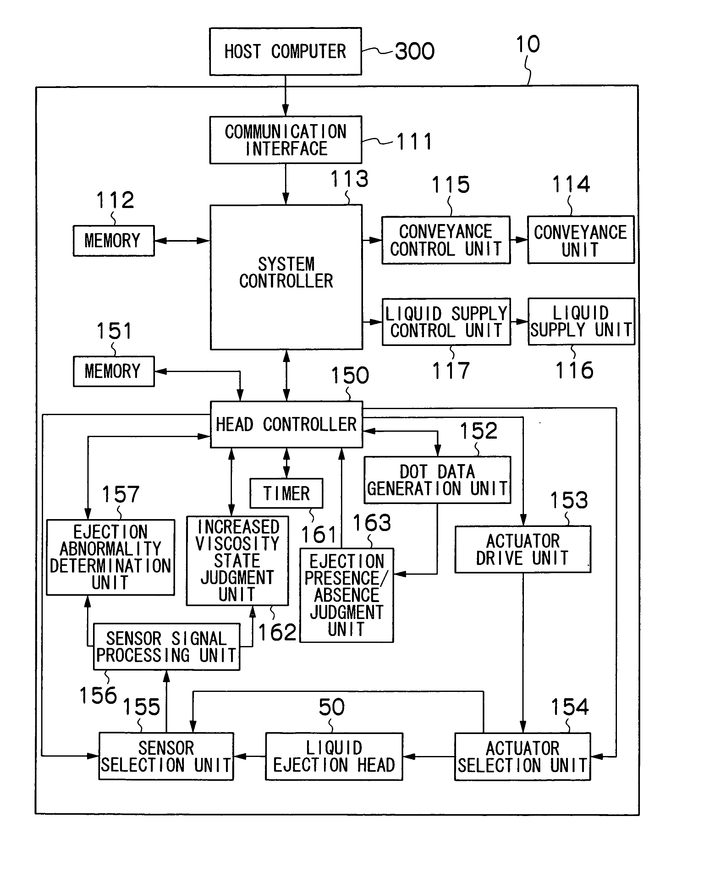
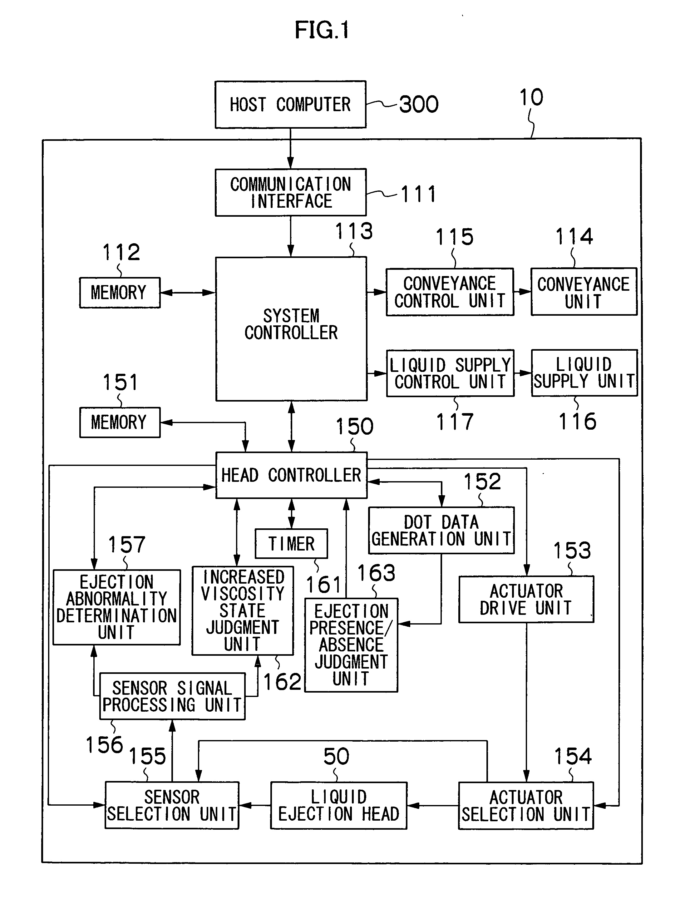
[0043]FIG. 1 is a block diagram showing the general composition of an image forming apparatus corresponding to a liquid ejection apparatus according to an embodiment of the present invention.

[0044] The image forming apparatus 10 shown in FIG. 1 comprises: a communication interface 111; memories 112 and 151; a system controller 113; a conveyance unit 114; a conveyance control unit 1115; a liquid supply unit 1116; a liquid supply control unit 117; a head controller 150; a dot data generation unit 152; an actuator drive unit 153; an actuator selection unit 154; a sensor selection unit 155; a sensor signal processing unit 156; an ejection abnormality determination unit 157; a timer 161; an increased viscosity state judgment unit 162; and an ejection presence / absence judgment unit 163.

[0045] The communication interface 111 is an image data input device for receiving image data transmitted by a host computer 300. For the communication inte...


PUM


Abstract

The liquid ejection apparatus comprises: a nozzle which ejects liquid; a pressure chamber which is connected to the nozzle; an actuator which generates pressure applied to the liquid inside the pressure chamber, the actuator driving liquid ejection for ejecting the liquid from the nozzle, the actuator driving vibrating action to the liquid for causing a free surface of the liquid in the nozzle to vibrate to an extent that does not eject the liquid from the nozzle; a viscosity state judgment device which judges viscosity states of the liquid in a vicinity of the free surface of the liquid in the nozzle, the viscosity states including a first state in which the liquid ejection from the nozzle is possible and the vibrating action is not required for the nozzle, a second state in which the liquid ejection from the nozzle is possible and the vibrating action is required for the nozzle, and a third state in which the liquid ejection from the nozzle is not possible and restoration to the first state is possible if the vibrating action is performed for the nozzle; and a control device which, in a case where the liquid ejection from the nozzle is to be performed, controls in the first state so as to perform the liquid ejection from the nozzle without performing the vibrating action for the nozzle, and controls in either one of the second state and the third state so as to perform the liquid ejection from the nozzle after performing the vibrating action for the nozzle, and which, in a case where the liquid ejection from the nozzle is not to be performed, controls in either one of the first state and the second state so as not to perform the vibrating action for the nozzle, and controls in the third state so as to perform the vibrating action for the nozzle.

Description

BACKGROUND OF THE INVENTION [0001] 1. Field of the Invention [0002] The present invention relates to a liquid ejection apparatus and a control method for a liquid ejection apparatus, and more particularly, to a liquid ejection apparatus and a control method for a liquid ejection apparatus in which vibrating action is performed to free surfaces of liquid in nozzles. [0003] 2. Description of the Related Art [0004] A liquid ejection apparatus is known which performs vibrating action to liquid in order to prevent the viscosity of the liquid from increasing nearby a free surface (the liquid-atmosphere interface, which is also commonly called “meniscus”) of the liquid inside a nozzle (a liquid ejection port). [0005] More specifically, as shown in FIG. 12A, the solvent of ink evaporates from the free surface of the ink in a nozzle 51 due to the difference in the vapor pressure of the solvent between the atmosphere and the ink in the nozzle 51, and as shown in FIG. 12B, the ink inside the n...

Claims


Application Information

Patent Timeline
IPC IPC(8): B41J2/195
CPCB41J2/165B41J2/1721B41J2/17509B41J2/17563B41J2002/16502B41J2002/14354B41J2/16502
Inventor NAGASHIMA, KANJI
Owner FUJIFILM CORP
Why Eureka
Try Eureka