
Display panel having a reflective layer therein

a technology of display panel and reflective layer, which is applied in non-linear optics, instruments, optics, etc., can solve the problems of achieve the effect of eliminating flicker generation of displayed images

Inactive Publication Date: 2007-04-05
INNOLUX CORP
View PDF2 Cites 4 Cited by
  • Summary
  • Abstract
  • Description
  • Claims
  • Application Information

AI Technical Summary

Benefits of technology

[0009] Therefore, the present invention relates to a liquid crystal display panel, wherein the flickers of the displayed image may be eliminated.
[0011] Moreover, the present invention relates to an electronic device that incorporates the novel LCD display panel, wherein the flickers of the displayed image may be eliminated.
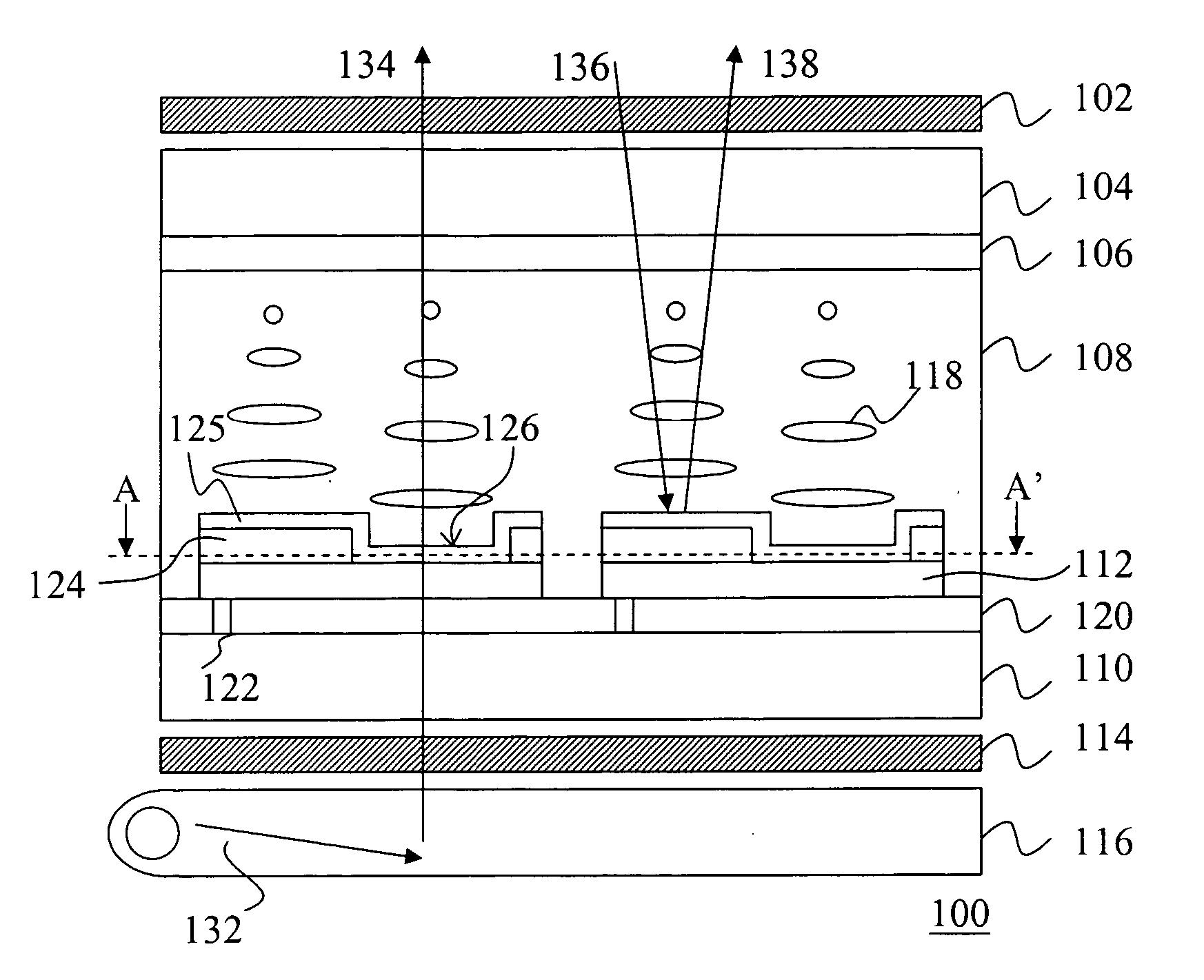
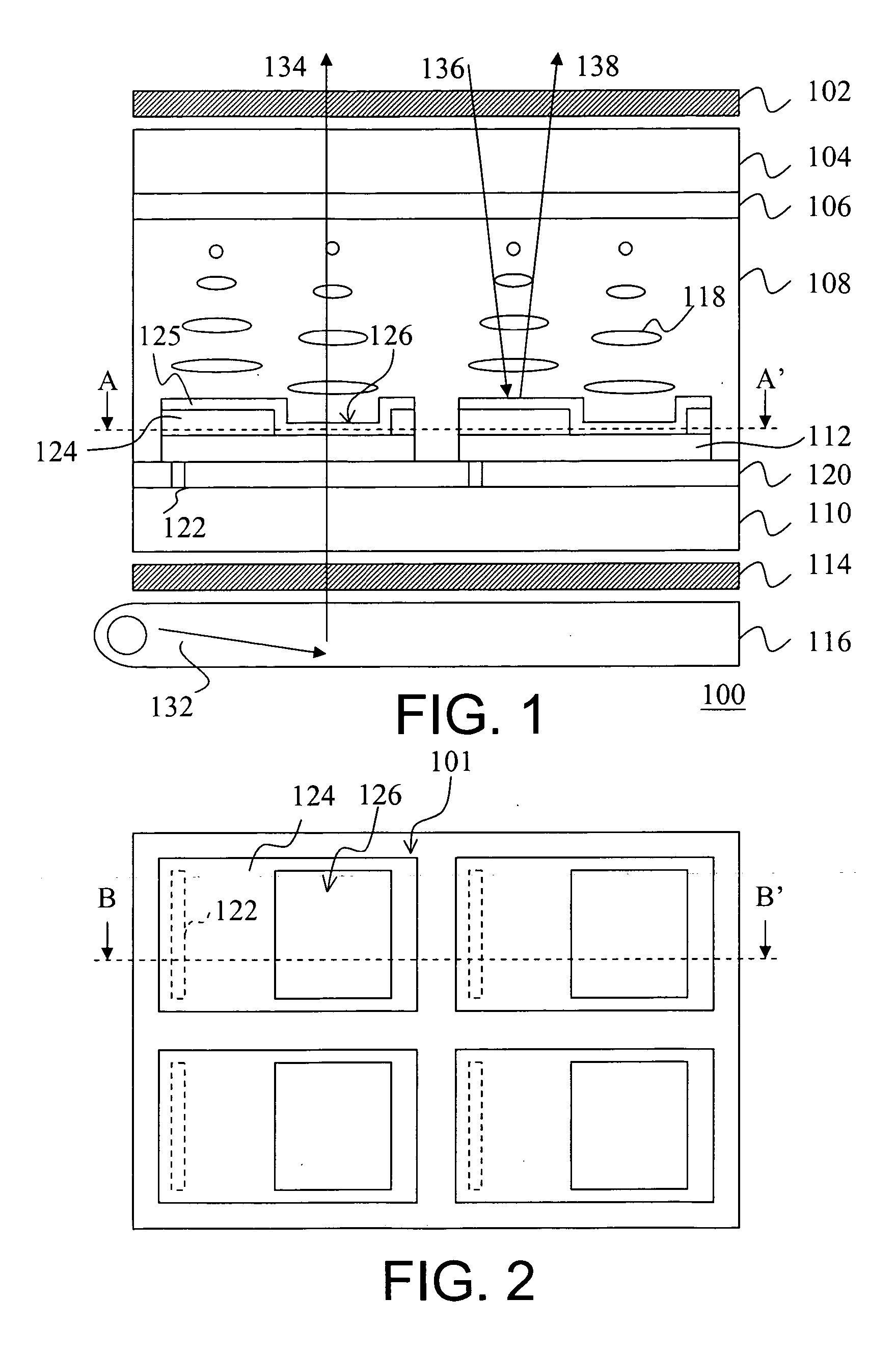
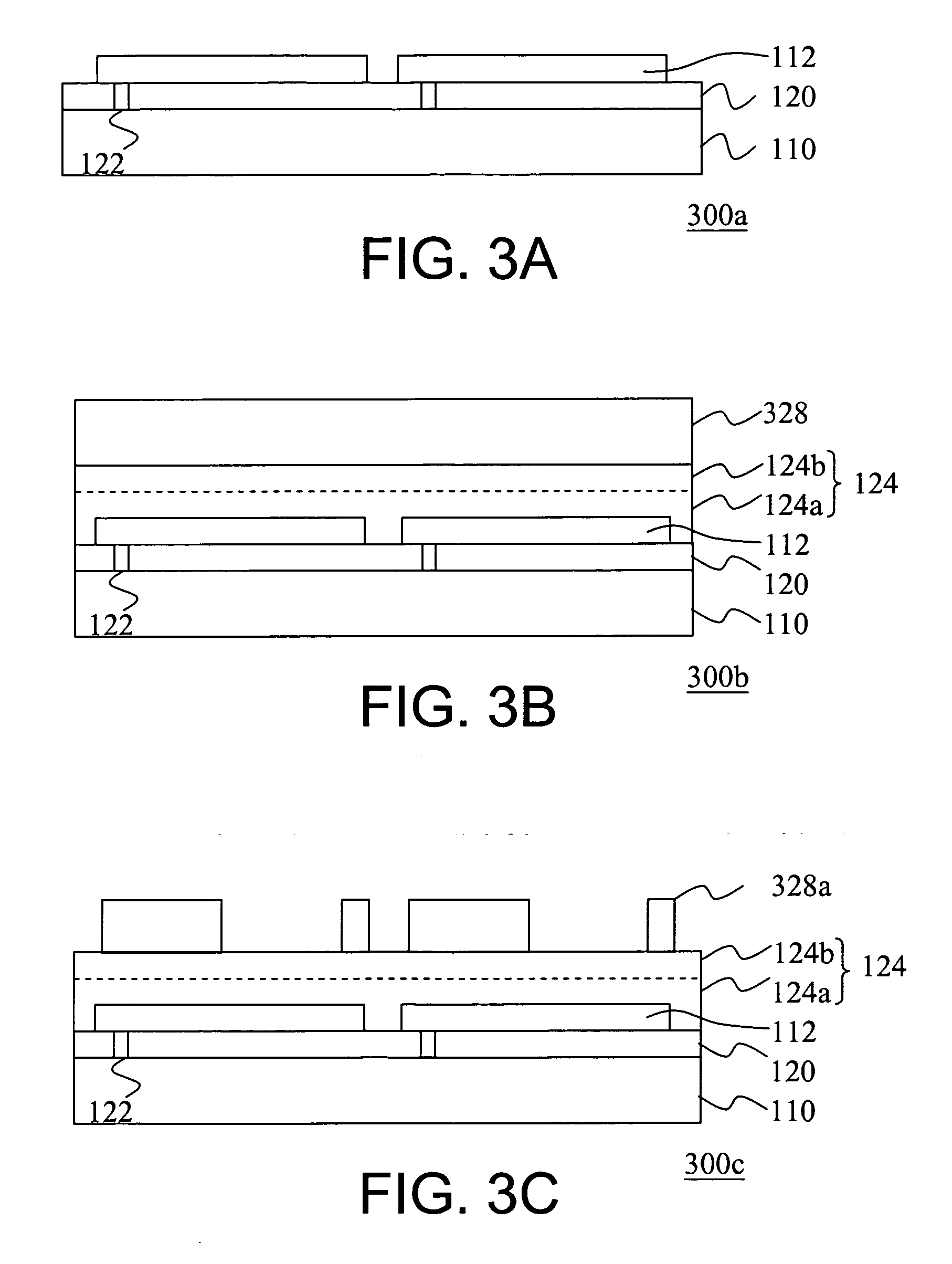
[0016] Accordingly, in the present invention, the reflective layer of the bottom substrate is disposed between the second transparent electrode and the cover layer. Since the first transparent electrode of the top substrate and the cover layer over the reflective layer of the bottom substrate may be composed of same material, the difference of the work function between the first transparent electrode of the top substrate and the cover layer of the bottom substrate may be minimized. Therefore, the flickers of the displayed image may be eliminated.

Problems solved by technology

However, the conventional transflective LCD has the disadvantages that flickers of the displayed image are generated due to the difference of the work function between the first transparent electrode on a top substrate and the reflection electrode on a bottom substrate.

Method used


Image

  • Display panel having a reflective layer therein
  • Display panel having a reflective layer therein
  • Display panel having a reflective layer therein

Examples


Embodiment Construction

[0029] The present invention now will be described more fully hereinafter with reference to the accompanying drawings, in which embodiments of the invention are shown. This invention may, however, be embodied in many different forms and should not be construed as limited to the embodiments set forth herein; rather, these embodiments are provided so that this disclosure will be thorough and complete, and will fully convey the scope of the invention to those skilled in the art. Like numbers refer to like elements throughout.

[0030]FIG. 1 is a schematic sectional view illustrating a transflective LCD according to one embodiment of the present invention. Referring to FIG. 1, the transflective LCD 100 comprises, for example but not limited to, a first polarizer 102, a first substrate 104, a first transparent electrode 106, a liquid crystal layer 108, a second substrate 110, a second transparent electrode 112, a second polarizer 114, a light source module 116, a reflective layer 124 and a...


PUM


Abstract

A liquid crystal display panel having a plurality of pixels is provided. Each pixel may include a first substrate, a second substrate, a liquid crystal layer, a reflective layer and a cover layer. A surface of the second substrate includes a second transparent electrode. The liquid crystal layer is disposed between the first substrate and the second substrate. The reflective layer is disposed over at least a portion of the second transparent electrode. The cover layer is disposed over the reflective layer.

Description

BACKGROUND OF THE INVENTION [0001] 1. Field of the Invention [0002] The present invention generally relates to a display device having a reflective layer therein. More particularly, the present invention relates to a structure of a liquid crystal display panel having a reflective layer therein, and a display device and electronic device using thereof. [0003] 2. Description of Related Art [0004] In recent years, conventional cathode ray tube (CRT) display has been gradually replaced by liquid crystal display (LCD) since LCD has advantages of small size, thinner thickness, light weight, large or small area, low operation voltage, power saving, and radiation free. Therefore, LCD has been gradually adopted for the display device of a variety of electronic products, specially the portable electronic products such as notebook computer, mobile phone, personal digital assistant (PDA) and so on. [0005] Conventionally, LCD is not self-illuminant, thus an external light source for liquid cryst...

Claims


Application Information

Patent Timeline
IPC IPC(8): G02F1/1335
CPCG02F1/133555
Inventor MORIMOTO, YOSHIHIROSHIH, ANTAI, YI-WEN
Owner INNOLUX CORP
Learn More