Pad area and method of fabricating the same

a technology of pad area and method, applied in the field of pad area, can solve the problems of defective devices, uneven operation of flat panel display,

Active Publication Date: 2007-04-05
SAMSUNG DISPLAY CO LTD
View PDF34 Cites 33 Cited by
  • Summary
  • Abstract
  • Description
  • Claims
  • Application Information

AI Technical Summary

Benefits of technology

[0010] The present invention is therefore directed to a pad area and a method of fabricating the same, which s

Problems solved by technology

In conventional conductive pad structures, however, contact errors may result when components are mounted due to a step difference between a passivation layer surrounding an edge of the conductive pad and

Method used


Image

  • Pad area and method of fabricating the same
  • Pad area and method of fabricating the same
  • Pad area and method of fabricating the same

Examples


Embodiment Construction

[0020] Korean Patent Application No. 2005-0092289, filed Sep. 30, 2005, in the Korean Intellectual Property Office, and entitled: “Pad Area and Method of Fabricating the Same,” is incorporated by reference herein in its entirety.

[0021] The present invention will now be described more fully hereinafter with reference to the accompanying drawings, in which exemplary embodiments of the invention are shown. The invention may, however, be embodied in different forms and should not be construed as limited to the embodiments set forth herein. Rather, these embodiments are provided so that this disclosure will be thorough and complete, and will fully convey the scope of the invention to those skilled in the art. In the figures, the dimensions of layers and regions are exaggerated for clarity of illustration.

[0022] It will also be understood that when a layer is referred to as being “on” another layer or substrate, it can be directly on the other layer or substrate, or intervening layers m...


PUM


Abstract

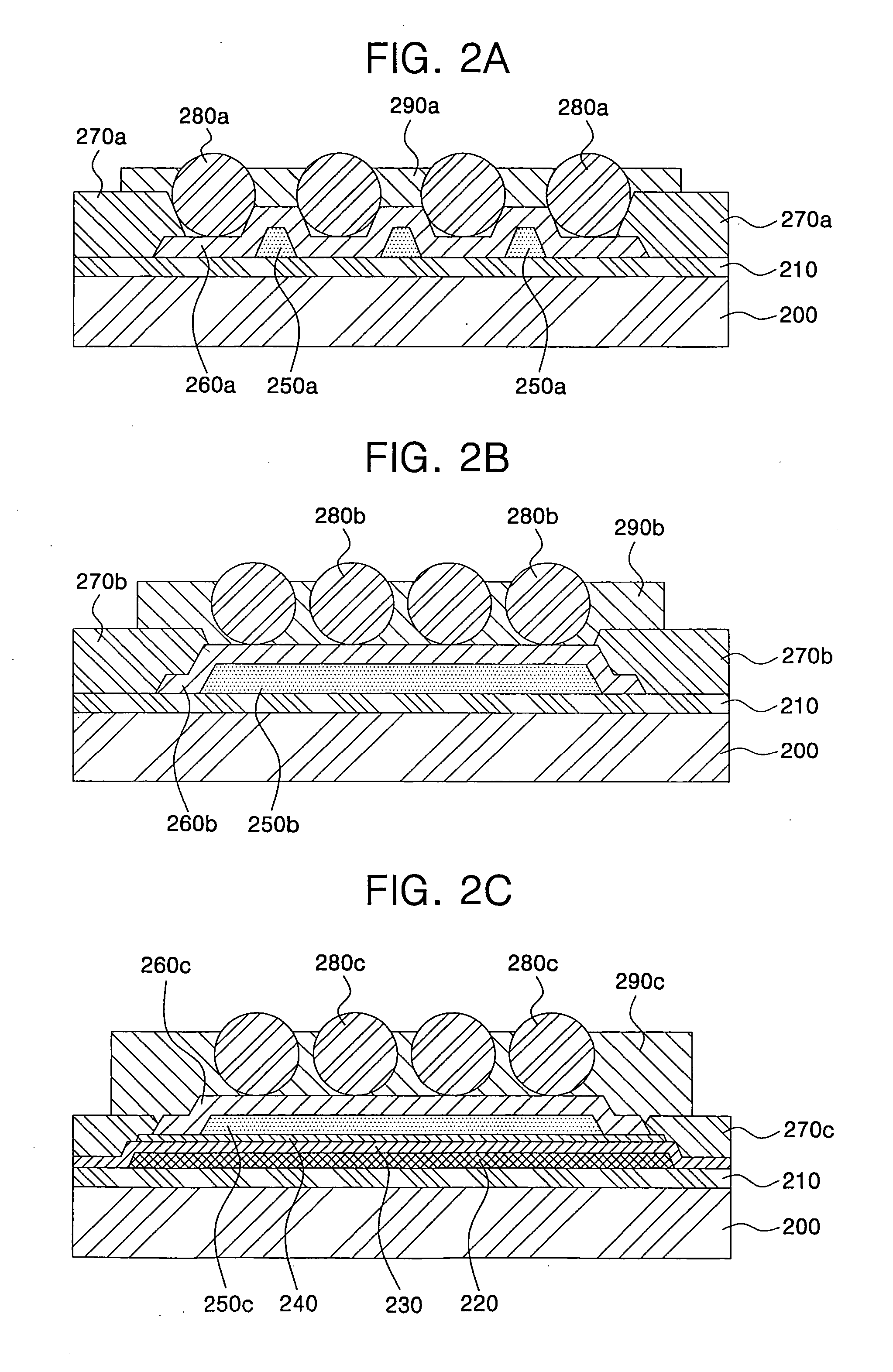
A pad area and a method of fabricating the same, wherein the pad area is formed on a substrate to contact a chip on glass (COG) or a chip on flexible printed circuit (COF) with the substrate. Changing a lower structure of the pad area increases contact points between conductive balls and an interconnection layer or reduces a step difference between an interconnection layer and a passivation layer to enhance and ensure electrical connection.

Description

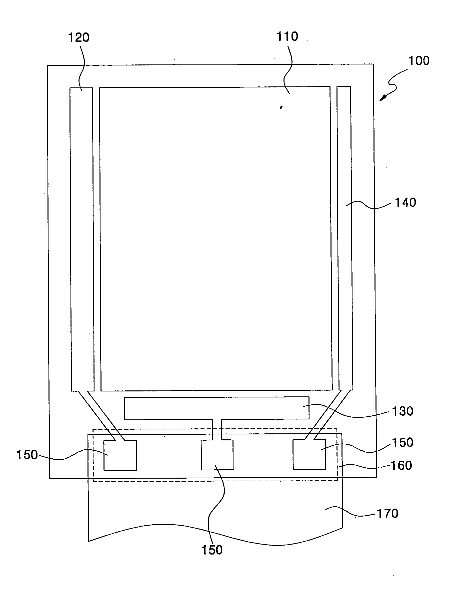
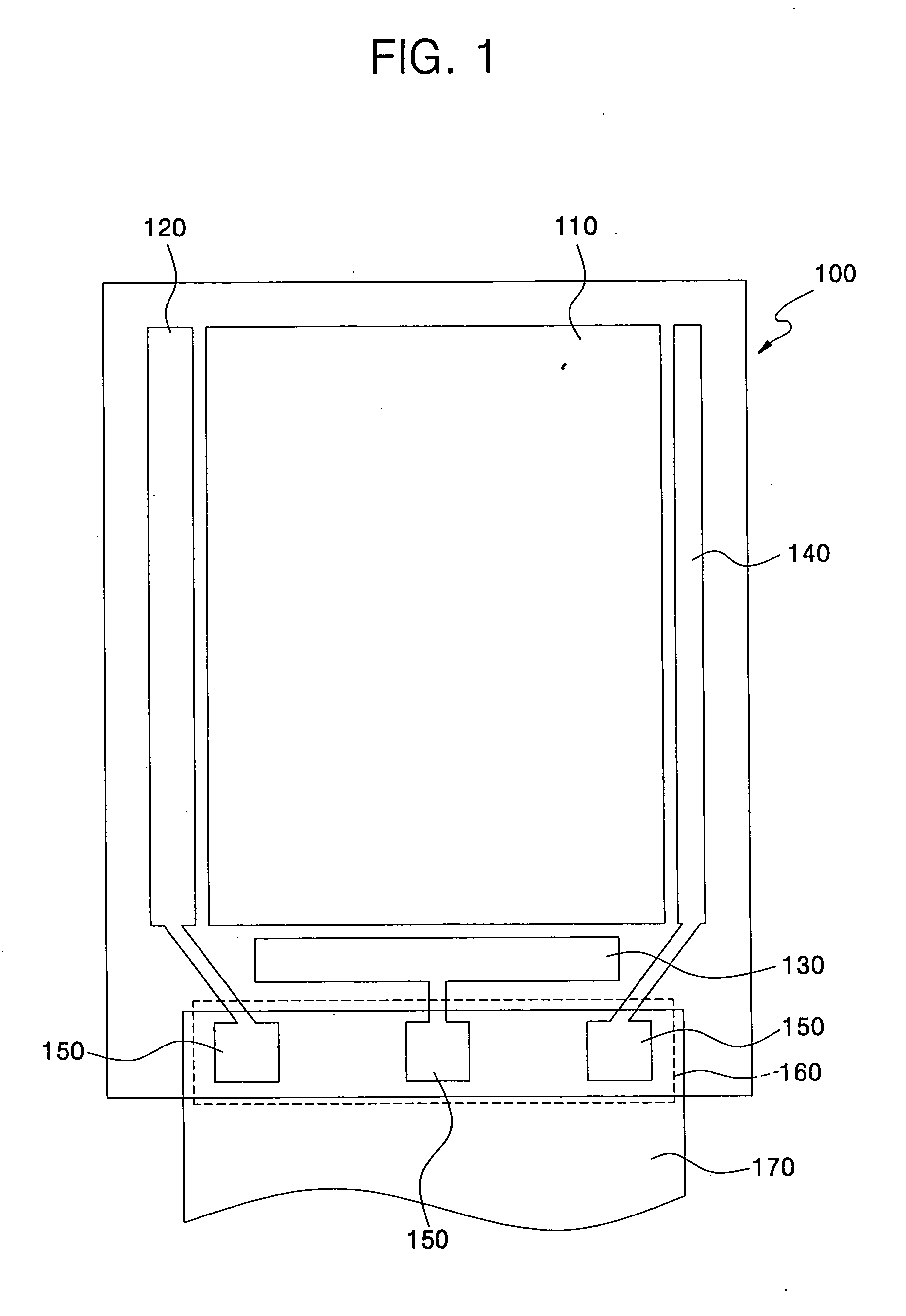
BACKGROUND OF THE INVENTION [0001] 1. Field of the Invention [0002] The present invention relates to a pad area and a method of fabricating the same. More particularly, the present invention relates to a pad area and a method of fabricating the same that are capable of improving contact characteristics of an interconnection layer and a conductive ball by additionally forming an embossed layer having a plurality of embossed patterns under the interconnection layer of the pad area to form embossments on the interconnection layer, or reducing a step difference between the interconnection layer and a passivation layer to minimize a contact error by additionally forming an embossed layer having a single embossed pattern in a multi-layer structure of a semiconductor layer, a gate insulating layer, a gate electrode, and so on. [0003] 2. Description of the Related Art [0004] Recently, in order to solve problems related to conventional cathode ray tube (CRT) displays, including weight and bu...

Claims


Application Information

Patent Timeline
IPC IPC(8): H05K7/12H05K7/10
CPCG02F1/13452G02F2001/13456H05K1/111H05K3/323H05K3/361H05K2201/0373Y02P70/50G02F1/13456G02F1/1345
Inventor JEONG, CHANG-YONGKANG, TAE-WOOKKWAK, WON-KYU
Owner SAMSUNG DISPLAY CO LTD
Why Eureka
Try Eureka