

Light source device, display device, and terminal device
- Summary
- Abstract
- Description
- Claims
- Application Information
AI Technical Summary
Benefits of technology
Problems solved by technology
Method used
Image

Examples
first embodiment
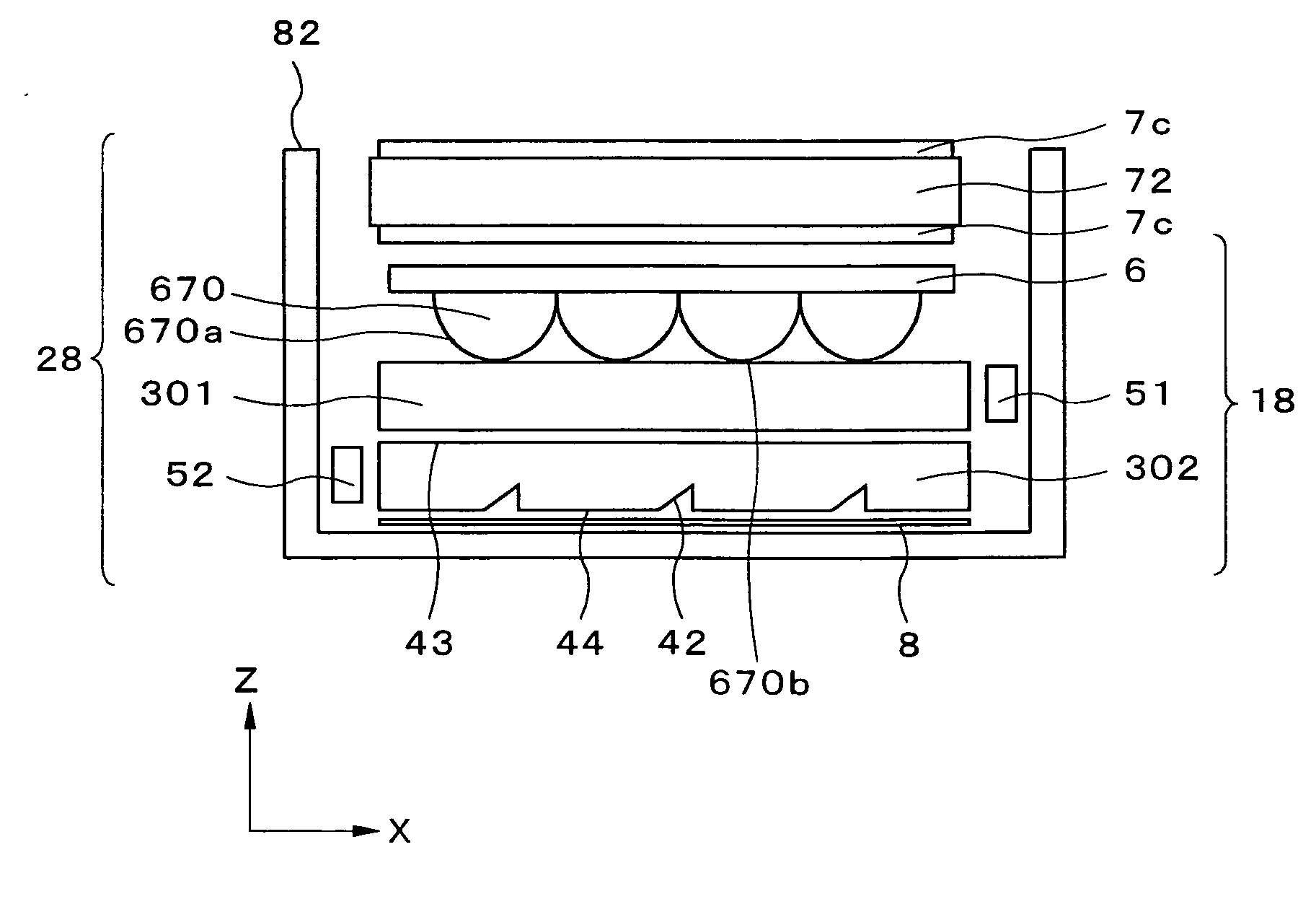
[0082] The light source device, display device that uses the light source device, and terminal device according to embodiments of the present invention will be described in detail hereinafter with reference to the accompanying drawings. The light source device, display device that uses the light source device, and terminal device according to the present invention will first be described. FIG. 4 is a sectional view showing the light source device according to the present embodiment; FIG. 5 is a sectional view showing the display device that uses the light source device; and FIG. 6 is a perspective view showing a mobile terminal device that is equipped with the display device that uses the light source device of the present embodiment.
[0083] As shown in FIG. 4, a light-guide plate 301, an emitted light control sheet 6 disposed facing the front surface of the light-guide plate 301, i.e., towards an observer; a second light-guide plate 302 disposed facing the back surface of the light-...
second embodiment
[0114] By placing the narrow-angle light source and the wide-angle light source in the same position with respect to the corresponding light-guide plates (a position on the surface on the −X side with respect to each light-guide plate in the present embodiment), the bottom surface area of the light source device can be reduced in comparison to a case in which the light sources are each disposed in different positions from the corresponding light-guide plates, as described in the present invention.
[0115] The display panel used in combination with the light source device of the present invention is not limited to a transmissive liquid crystal panel, and any display panel that uses a light source device may be used. However, a liquid crystal panel is suitable that has minimal dependence on viewing angle. Examples of the mode of such a liquid crystal panel include IPS (In-Plane Switching), FFS (Fringe Field Switching), AFFS (Advanced Fringe Field Switching), and the like among horizonta...
PUM
 Abstract
Description
Claims
Application Information