Multi-layered media aberration compensation apparatus, method, and system

Inactive Publication Date: 2007-04-05
IBM CORP
View PDF10 Cites 0 Cited by
  • Summary
  • Abstract
  • Description
  • Claims
  • Application Information

AI Technical Summary

Benefits of technology

[0016] A method of the present invention is also presented to compensate for aberration. The method in the disclosed embodiments substantially includes the steps necessary to carry out the functions presented above with respect to the operation of the described apparatus and system. In one embodiment, the method includes interleaving a plurality of electrodes with a plurality of compensation planes and providing a

Problems solved by technology

Although the laser has multiple intensities to accommodate each data layer, the laser is typically set at a fixed focal length resulting in increased data error rates over single layer optical media.
Additional challenges result from the va

Method used


Image

  • Multi-layered media aberration compensation apparatus, method, and system
  • Multi-layered media aberration compensation apparatus, method, and system
  • Multi-layered media aberration compensation apparatus, method, and system

Examples


Embodiment Construction

[0027] Many of the functional units described in this specification have been explicitly labeled as modules, in order to more particularly emphasize their implementation independence. For example, a module may be implemented as a hardware circuit comprising custom VLSI circuits or gate arrays, off-the-shelf semiconductors such as logic chips, transistors, or other discrete components. A module may also be implemented in programmable hardware devices such as field programmable gate arrays, programmable array logic, programmable logic devices or the like.

[0028] Modules may also be implemented in software for execution by various types of processors. An identified module of executable code may, for instance, comprise one or more physical or logical blocks of computer instructions which may, for instance, be organized as an object, procedure, or function. Nevertheless, the executables of an identified module need not be physically located together, but may comprise disparate instructio...


PUM


Abstract

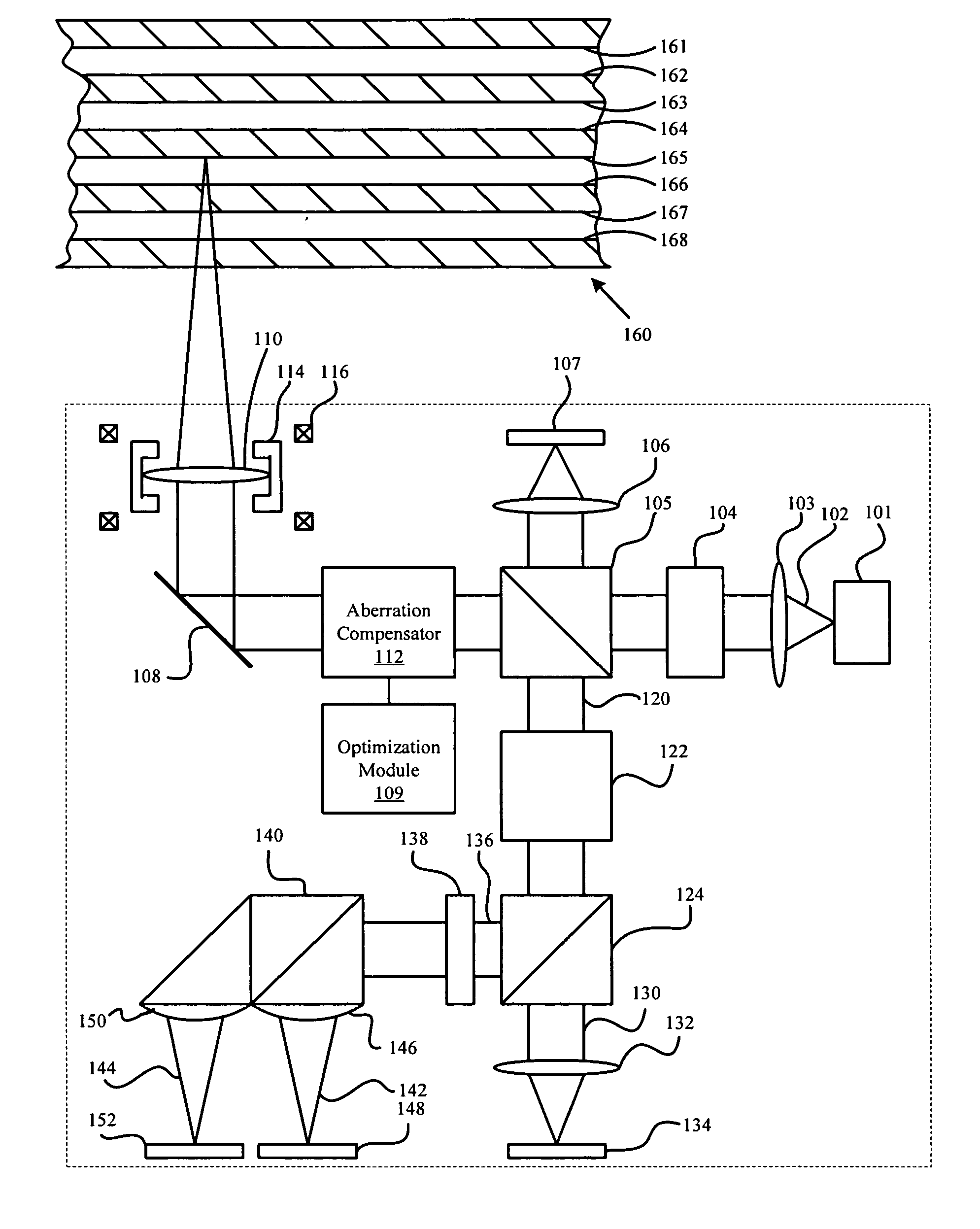
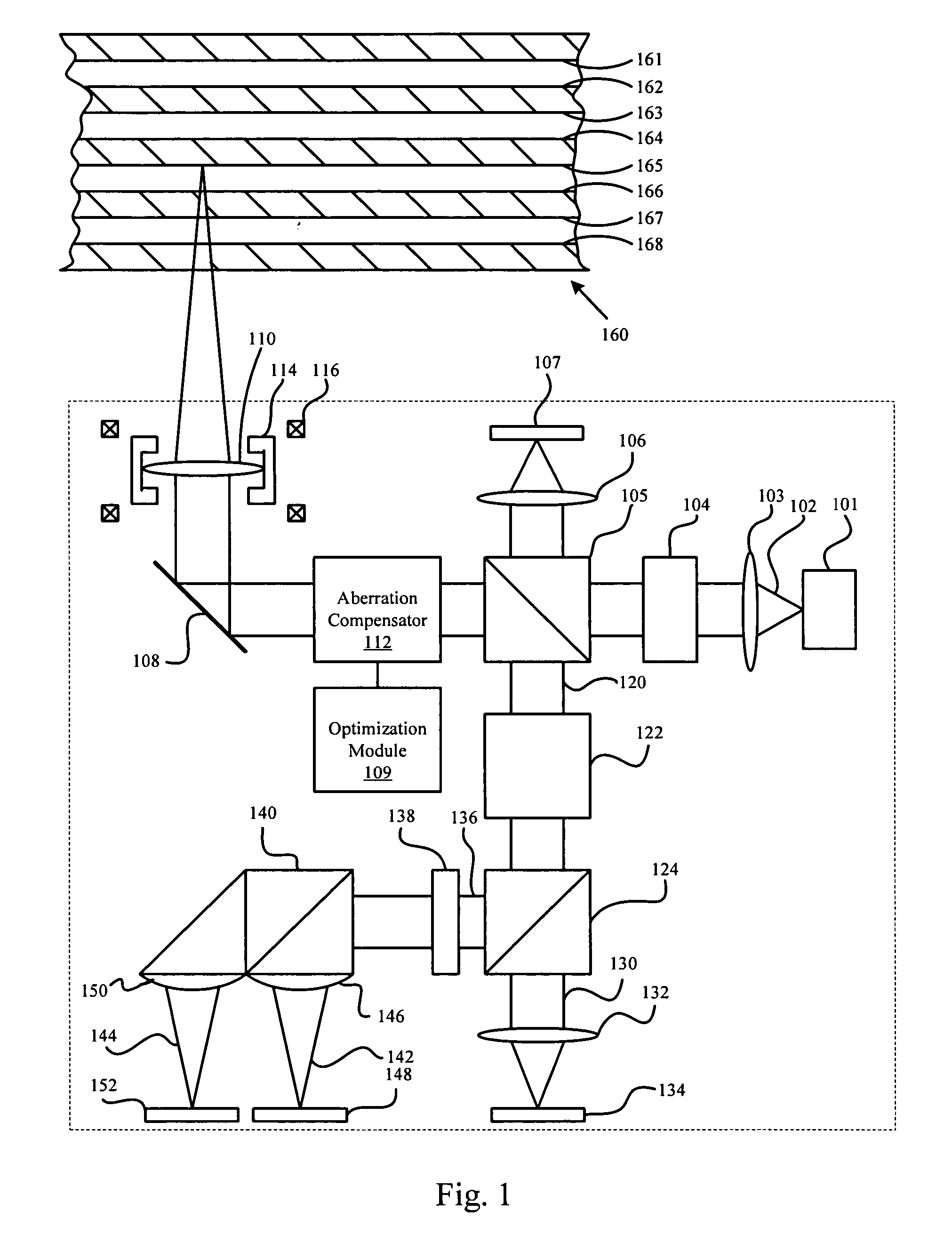
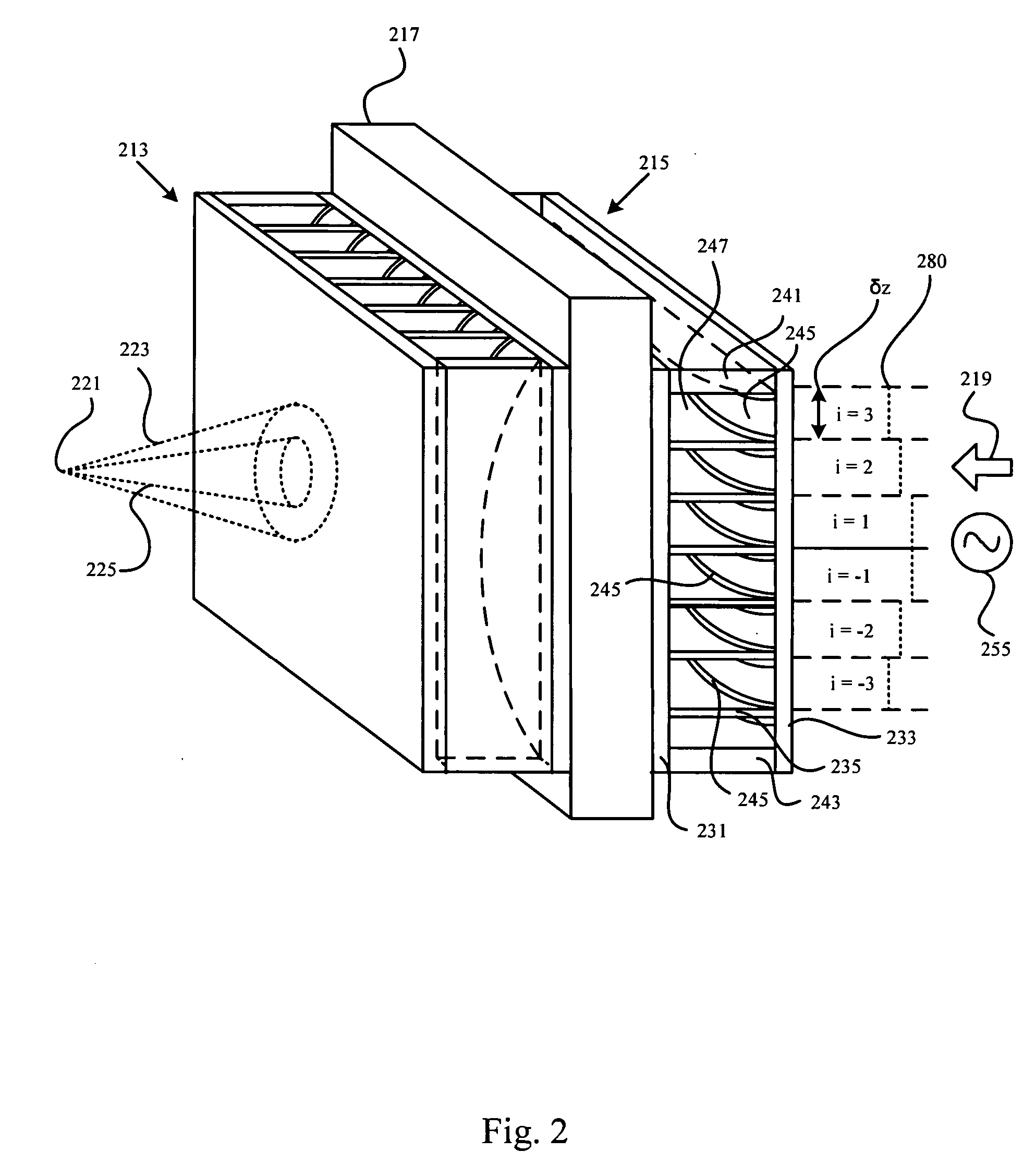
An apparatus, system, and method are disclosed for aberration compensation. In one embodiment, a first compensation lens used in conjunction with a second compensation lens to produce a conical beam used to read from, or write to, an optical medium. An Nth order compensation equation is used to optimize aberration errors associated with accessing the optical medium. The present invention may include a displaceable focus lens positioned relative to an optical medium. The focus lens may be displaced when the conical beam's focal length is adjusted. A displacement equation is presented to determine the preferred placement of the focus lens. By compensating for aberration, read/write errors may be reduced while accessing optical media thus increasing system robustness and facilitating the use of additional layers on optical media.

Description

BACKGROUND OF THE INVENTION [0001] 1. Field of the Invention [0002] This invention relates to aberration compensation and more particularly relates to apparatus, methods, and systems for compensating for aberration when accessing an optical medium. [0003] 2. Description of the Related Art [0004] Optical media have become increasing pervasive in digital systems. Movies, pictures, and other familiar content, as well as software programs, drivers, and data can all be stored in a non-volatile manner on optical media. Because the use of optical media is so flexible and pervasive, the motivation to increase storage density has increased. One approach to increasing the storage density of optical media involves the use of multiple data layers. [0005] Accessing an optical media with multiple layers is typically accomplished by using a single laser and selecting a unique intensity for each data layer. For example, one intensity is set for the data layer closest to the laser, another intensity...

Claims


Application Information

Patent Timeline
IPC IPC(8): G11B7/135G11B7/00
CPCG11B7/1369G11B7/1378G11B7/13925G11B2007/0013
Inventor HAUSTEIN, NILSKLEIN, CRAIG ANTHONYWINARSKI, DANIEL JAMES
Owner IBM CORP
Why Eureka
Try Eureka