Optical system with optical image stabilization using a MEMS mirror

an optical system and optical image technology, applied in the field of optical systems, can solve the problems of optical systems such as lens modules, telescopes, other portable imaging devices, prone to movement during imaging process, and optical systems to have slow response time, etc., to achieve the effect of light weight, simple operation and fast speed

Active Publication Date: 2014-04-01
STEREO DISPLAY
View PDF6 Cites 8 Cited by
  • Summary
  • Abstract
  • Description
  • Claims
  • Application Information

AI Technical Summary

Benefits of technology

[0007]The optical system with optical image stabilization of the present invention are contrived to provide fast speed, light weight, simple operation, and high image quality image stabilization for the optical system.
[0019]The reflective element can be a mirror configured to fold the optical paths of the light, which makes the optical system compact.
[0020]The reflective element is movable and configured to adjust the focus of the optical system. The movable reflective element can be a Micromirror Array Lens, wherein the Micromirror Array Lens is a variable focus lens configured to change the effective focal length of the optical system, wherein the Micromirror Array Lens comprises a plurality of micromirrors and changes the effective focal length of the optical system by controlling the motions of the micromirrors. In addition, the Micromirror Array Lens can compensate aberrations of the optical system by controlling the motions of the micromirrors.

Problems solved by technology

Optical systems such as lens modules, still cameras, video cameras, telescopes and other portable imaging devices are prone to have a movement during imaging process.
These movements can cause a critical problem especially in long exposure time (low light condition) or with long focal length setting (telephoto) by resulting in severely blurred images.
The macroscopic movement or macroscopic shape change of the optical elements can cause the optical system to have slow response time, increased volume and weight, complex structure and operation, and eventually low image quality.

Method used


Image

  • Optical system with optical image stabilization using a MEMS mirror
  • Optical system with optical image stabilization using a MEMS mirror
  • Optical system with optical image stabilization using a MEMS mirror

Examples


Embodiment Construction

[0040]The present invention will now be described in detail with reference to a few embodiments thereof as illustrated in the accompanying drawings. In the following description, numerous specific details are set forth in order to provide a thorough understanding of the present invention. It will be apparent, however, to one skilled in the art, that the present invention may be practiced without some or all of these specific details. In other instances, well known process steps and / or structures have not been described in detail in order to not unnecessarily obscure the present invention.

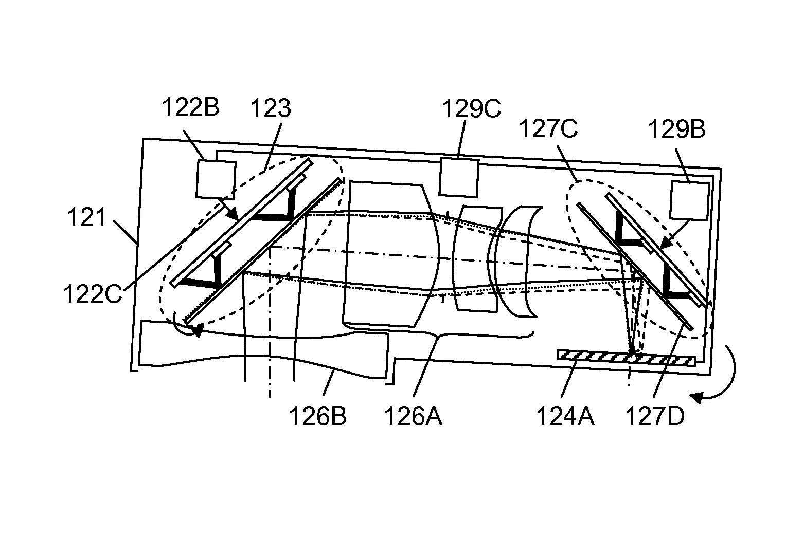
[0041]The optical device with optical image stabilization of the present invention compensates the movement of the optical system occurring during imaging process to improve image quality.

[0042]FIGS. 3a-3b are schematic diagrams showing embodiments of an optical system with optical image stabilization of the present invention. As shown in FIG. 3a, the optical system 31 with optical image stabilizati...


PUM


Abstract

An optical system with optical image stabilization of the present invention compensates the movement of the optical system occurring during imaging process using a Micro-Electro Mechanical System (MEMS) unit having an MEMS mirror to stabilize an image of an object formed on an image plane. A micro-actuator with the in-plane translation makes the MEMS mirror have a required rotation to change optical paths of light from the object to the image plane for optical image stabilization. The optical system with optical image stabilization or the present invention provides fast speed, light weight, simple operation, and high image quality image stabilization for the optical system.

Description

FIELD OF THE INVENTION[0001]The present invention relates to an optical system in general and more specifically to an optical system with optical image stabilization.BACKGROUND OF THE INVENTION[0002]Optical systems such as lens modules, still cameras, video cameras, telescopes and other portable imaging devices are prone to have a movement during imaging process. The movement of the optical systems can come from many sources including hand shaking (e.g. in still or video cameras), environmental vibration (e.g. in moving vehicles), and / or earth's rotation (e.g. in astronomical applications). These movements can cause a critical problem especially in long exposure time (low light condition) or with long focal length setting (telephoto) by resulting in severely blurred images.[0003]Various approaches for image stabilization have been developed in order to compensate the movement of the optical system occurring during the imaging process. These include mechanical image stabilization, op...

Claims


Application Information

Patent Timeline
Patent Type & Authority Patents(United States)
IPC IPC(8): G02B27/64G02B26/08
CPCG02B26/0833G02B27/64G02B27/646
Inventor CHO, GYOUNG ILKIM, HYE YOUNGSEO, CHEONG SOO
Owner STEREO DISPLAY
Why Eureka
Try Eureka