Multihybrid Artificial Compound Eye with Varied Ommatidia

Active Publication Date: 2012-02-02
SPECTRAL IMAGING LAB
View PDF0 Cites 9 Cited by
  • Summary
  • Abstract
  • Description
  • Claims
  • Application Information

AI Technical Summary

Benefits of technology

[0038]It is another object of the invention to provide a means for reducing the effective F-number of a system by allowing beams from adjacent ommatidia of the same field angle to superpose at the final

Problems solved by technology

Single aperture optics have the advantage of good spatial resolution and efficient light capture, but they are disadvantaged by their relatively large size and limited field of view.
The classical solution of adding spherically shaped optical elements does not eliminate distortion, and it yields a lens that is heavy and long.
The excessive use of aspheric surfaces in modern wide angle systems highlights a fundamental contradiction in conventional optical design principles: Aberrations increase exponentially as the field angle and pupil size increase laterally away from the central optical axis; designers can only correct for these laterally induced aberrations indirectly by adding and altering optical surfaces sequentially along the central optical axis.
Another disadvantage of the high resolution, single aperture lens is its need for focus adjustment to image objects at different distances.
As with all such auto focusing schemes, it cannot overcome the inherent design limitation of a single aperture lens: Objects at different depths of field cannot be brought into focus simultaneously.
Wide angle single aperture lens systems are also unable to generate images with uniform intensity.
A double pupil plane design can limit the intensity degradation to about 50% but cannot eliminate the problem entirely.
Single aperture lens systems are inherently prone to stray light degradation, even when designed with an intermediate field stop.
However, even with the extended baffle, the best systems

Method used


Image

  • Multihybrid Artificial Compound Eye with Varied Ommatidia
  • Multihybrid Artificial Compound Eye with Varied Ommatidia
  • Multihybrid Artificial Compound Eye with Varied Ommatidia

Examples


Embodiment Construction

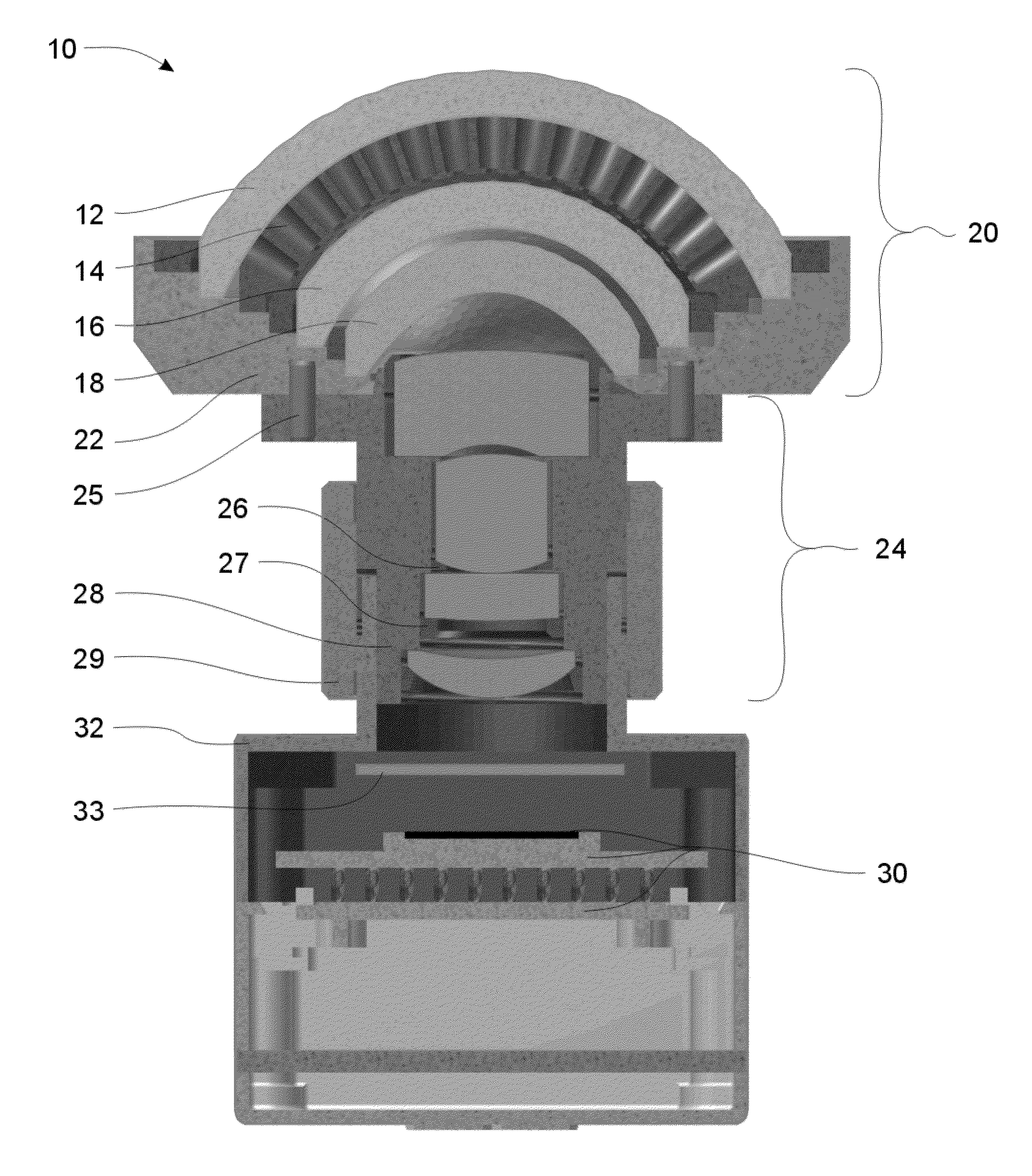
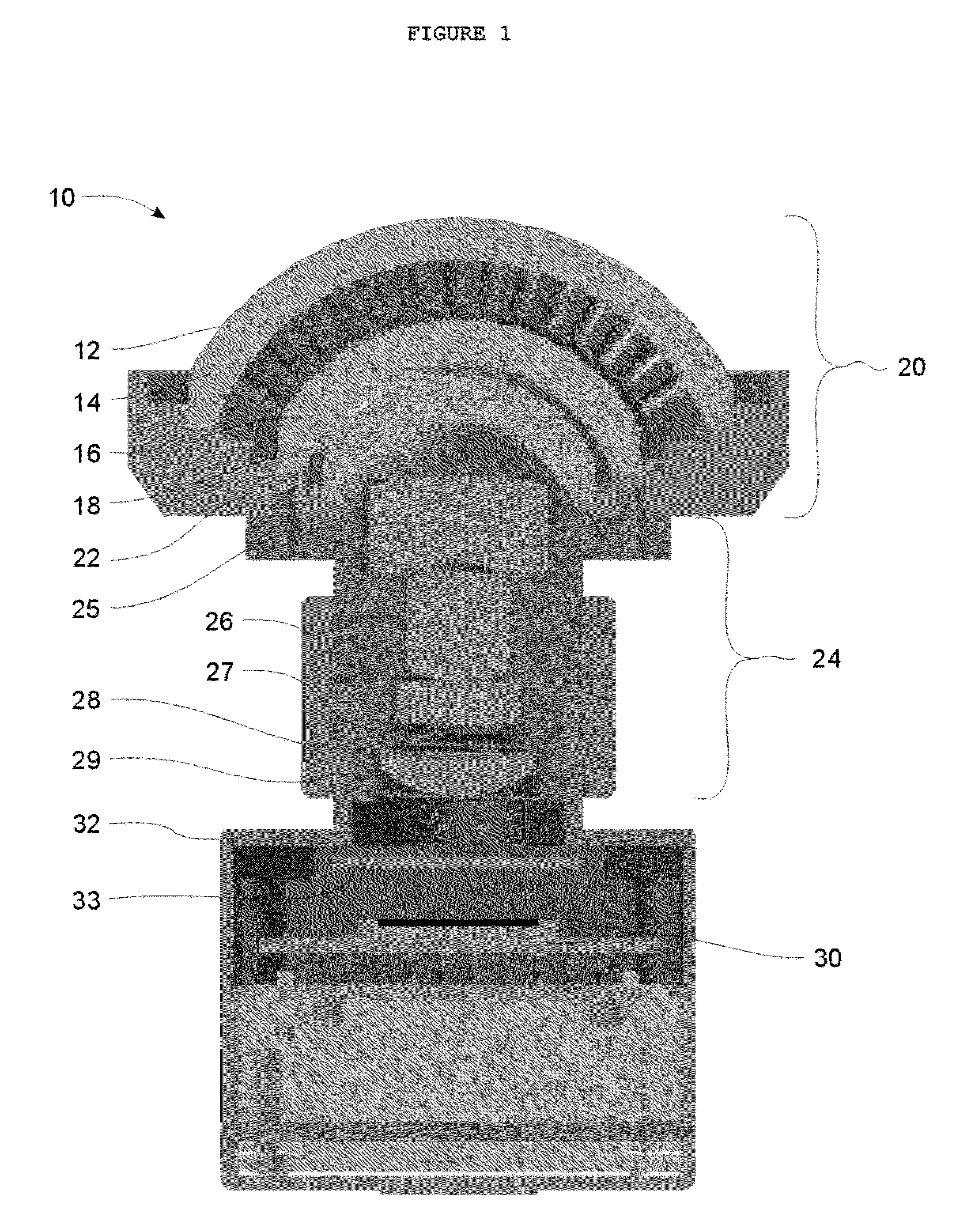
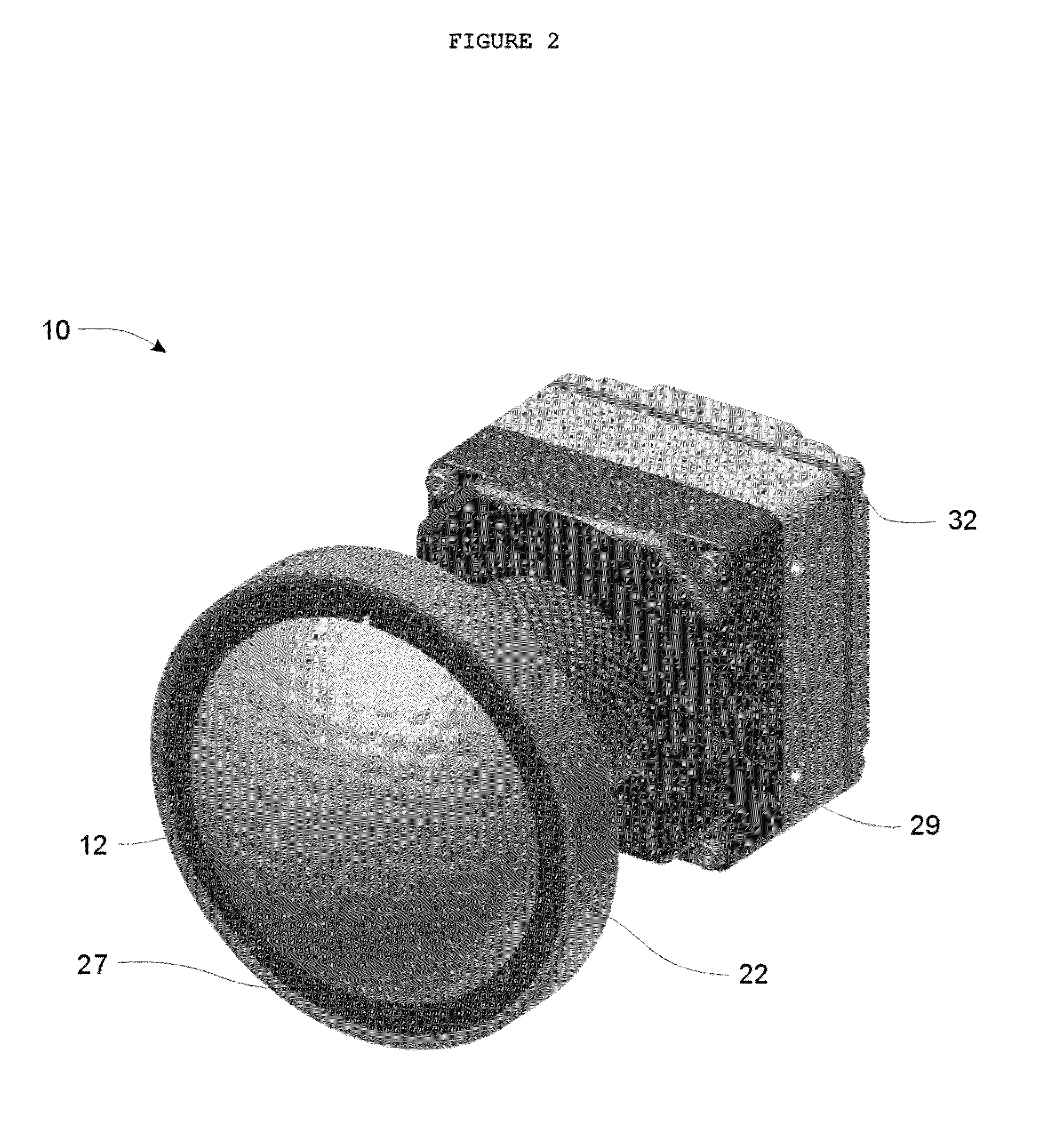
[0068]Referring now to the drawings, FIG. 1 is a cross-sectional view of a multihybrid artificial compound eye 10 constructed in accordance with one embodiment of the invention, and FIG. 2 is a front perspective view of the same system. The optics are divided into a hybrid superposition-apposition compound array fore-optic 20 and a rear-optic relay 24. The fore-optic includes an objective lenslet superposition array 12, a louver baffle 14, a field lenslet superposition array 16, and an erector lenslet apposition array, 18, all held rigidly in alignment by a fore-optic mounting structure 22. Each lenslet array is shaped conformally to a positive meniscus base with curvatures that are concentric. Each positive meniscus base is held in place by a retaining ring 27.

[0069]The rear-optic includes several conventional lens elements and an aperture stop that can be an iris 26, all held rigidly in alignment by a rear-optic mounting structure 28. Each lens element is held in place by a retain...


PUM


Abstract

A wide angle imaging system combines compound array fore-optics with single axis relay optics to generate distortion free images with an infinite depth of field. A curved first array of objective lenslets focuses multiple apertures of light through the tubes of a louver baffle terminated by field stops. An intermediate curved array of field lenslets, positioned immediately after the field stops, passes the light beams through an array of pupil planes. A curved final array of erector lenslets refocuses and adjoins the beams into a contiguous image that is curved. The relay optics transform the curved intermediate image into a flat final image. The fore-optics and relay optics are optimized concurrently to achieve much higher performance than is possible in either compound array optics or sequential optics. This is accomplished by varying the lenslet radii of the fore-optics in annular increments to compensate for aberrations introduced by the relay lenses.

Description

RELATED APPLICATIONS[0001]The present application is a continuation-in-part application of U.S. provisional patent application Ser. No. 61 / 370,084, filed Aug. 2, 2010, for MULTIHYBRID ARTIFICIAL COMPOUND EYE WITH VARIED OMMATIDIA, by Francis Mark Reininger, included by reference herein and for which benefit of the priority date is hereby claimed.FIELD OF THE INVENTION[0002]The present invention relates to wide angle imaging systems and, more particularly, to high resolution multiple aperture wide angle imaging systems with lenslet arrays coupled to sequential, single element lenses.BACKGROUND OF THE INVENTION[0003]Conventional camera optics are derived from the eyes of vertebrates, wherein a single lens system captures light through a large aperture and focuses it onto a concave retina. Single aperture optics have the advantage of good spatial resolution and efficient light capture, but they are disadvantaged by their relatively large size and limited field of view. Vertebrates evol...

Claims


Application Information

Patent Timeline
IPC IPC(8): G02B27/12
CPCG02B13/06
Inventor REININGER, FRANCIS MARK
Owner SPECTRAL IMAGING LAB
Why Eureka
Try Eureka