Use Of Papilla Mapping To Determine A Friction-Ridge Surface

Active Publication Date: 2007-04-05
QUALCOMM INC
View PDF6 Cites 107 Cited by
  • Summary
  • Abstract
  • Description
  • Claims
  • Application Information

AI Technical Summary

Benefits of technology

[0010] An embodiment of the invention may make use of physiological features of skin below the epidermis to obtain an image that is representative of a friction-ridge. That image may be sufficiently accurate so as to be suitable for identification purposes. FIGS. 1, 2 and 3, depict the skin on a finger. The rid

Problems solved by technology

The friction-ridge surface of the skin may be superficially damaged such that it

Method used


Image

  • Use Of Papilla Mapping To Determine A Friction-Ridge Surface
  • Use Of Papilla Mapping To Determine A Friction-Ridge Surface
  • Use Of Papilla Mapping To Determine A Friction-Ridge Surface

Examples


Embodiment Construction

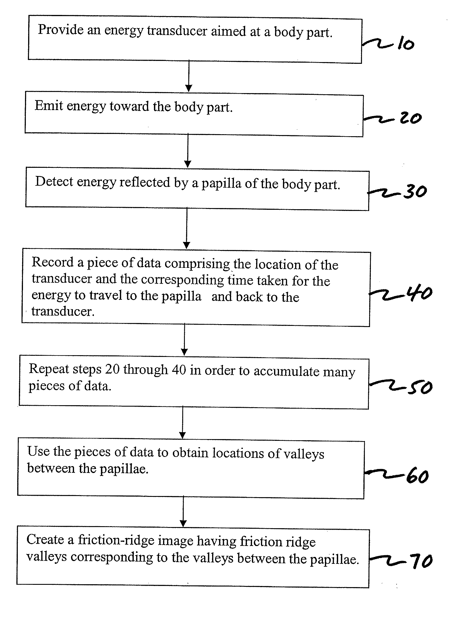
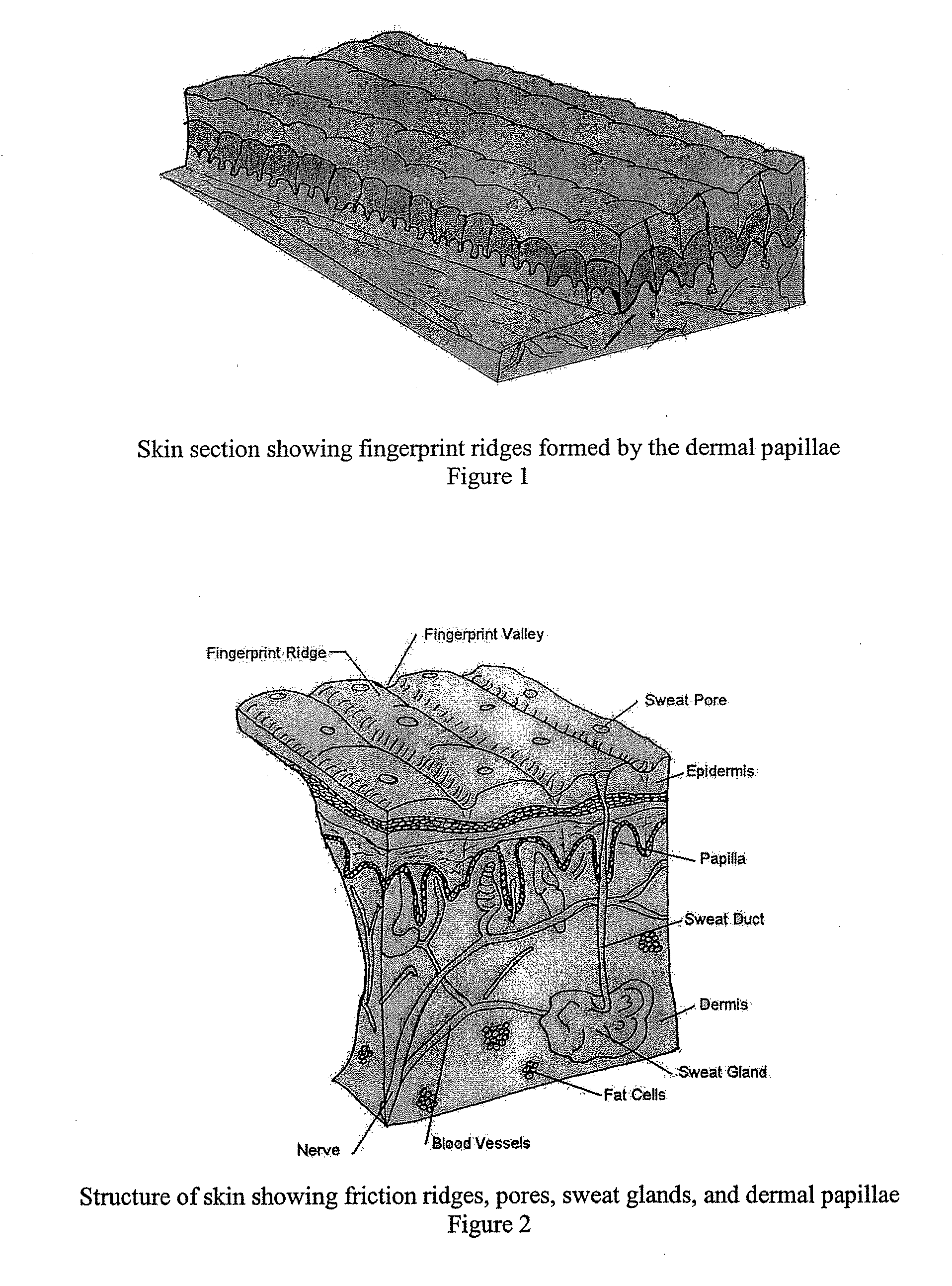
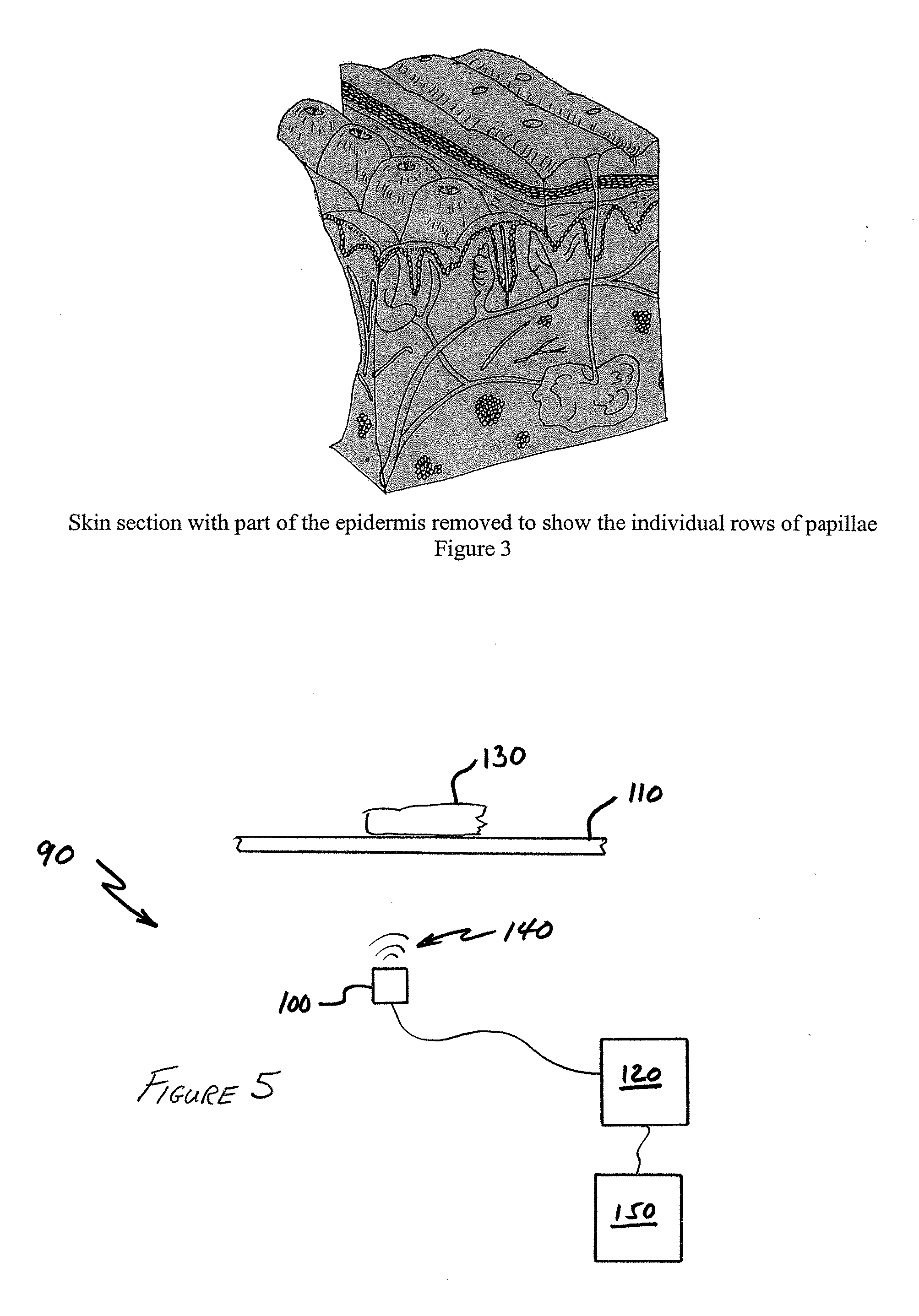
[0018] Generally speaking, the invention may provide a method by which morphological information is obtained from a portion of skin that is below the epidermis and that information is used predict an image of the friction-ridge surface that would likely result. In an embodiment of the invention information about the dermal papillae is obtained, and then that information is used to create an image of the epidermal layer that would likely result from such an arrangement of the dermal papillae.

[0019] The invention is described using fingerprints, but the invention is not limited to use with fingerprints. In one embodiment of the invention, it is assumed that the dermal papillae substantially define the structure of the fingerprint, such that valleys in the dermal papillae correspond to valleys in the fingerprint, and ridges of the dermal papillae correspond to ridges in the fingerprint. By using information derived from the dermal papillae and processing this information, the fingerpr...


PUM


Abstract

A method of creating a friction-ridge image is disclosed. An energy transducer is aimed at a body part having skin. The transducer is used to obtain information about the papillae beneath an outer surface of the skin. The information about the papillae is used to obtain information about valleys between the papillae, and a friction-ridge image having friction-ridge valleys that correspond with the valleys between the papillae is created.

Description

CROSS-REFERENCE TO RELATED APPLICATIONS [0001] This application claims the benefit of priority to U.S. provisional patent application Ser. No. 60 / 708,892, filed on Aug. 17, 2005.FIELD OF THE INVENTION [0002] The present invention relates to devices and methods of identifying an individual using biometrics. BACKGROUND OF THE INVENTION [0003] Biometric identification systems frequently encounter situations where the body part that is used to establish a biometric identity has been damaged. For example, a friction-ridge surface of a finger (a fingerprint) may be damaged by an accidental burn or abrasion to the finger. Intentional damage to a finger may also impede the ability of a biometric identification system to make a proper identification. Intentional damage may be inflicted in order to prevent identification, for example by abrading, burning or etching the friction-ridge surface. As an example, in Europe people applying for political asylum have burned off their fingerprints in o...

Claims


Application Information

Patent Timeline
IPC IPC(8): G06K9/00
CPCG06K9/0002G06V40/1306G06V40/12
Inventor SCHNEIDER, JOHN K.KITCHENS, JACK C.
Owner QUALCOMM INC
Why Eureka
Try Eureka