Increased aperture homing cavitator

Inactive Publication Date: 2007-04-05
GEN DYNAMICS INFORMATION TECH
View PDF2 Cites 15 Cited by
  • Summary
  • Abstract
  • Description
  • Claims
  • Application Information

AI Technical Summary

Benefits of technology

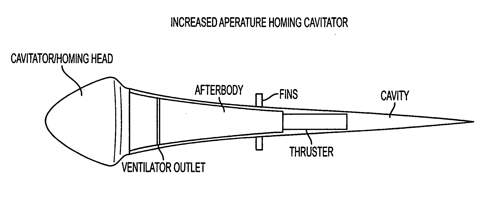
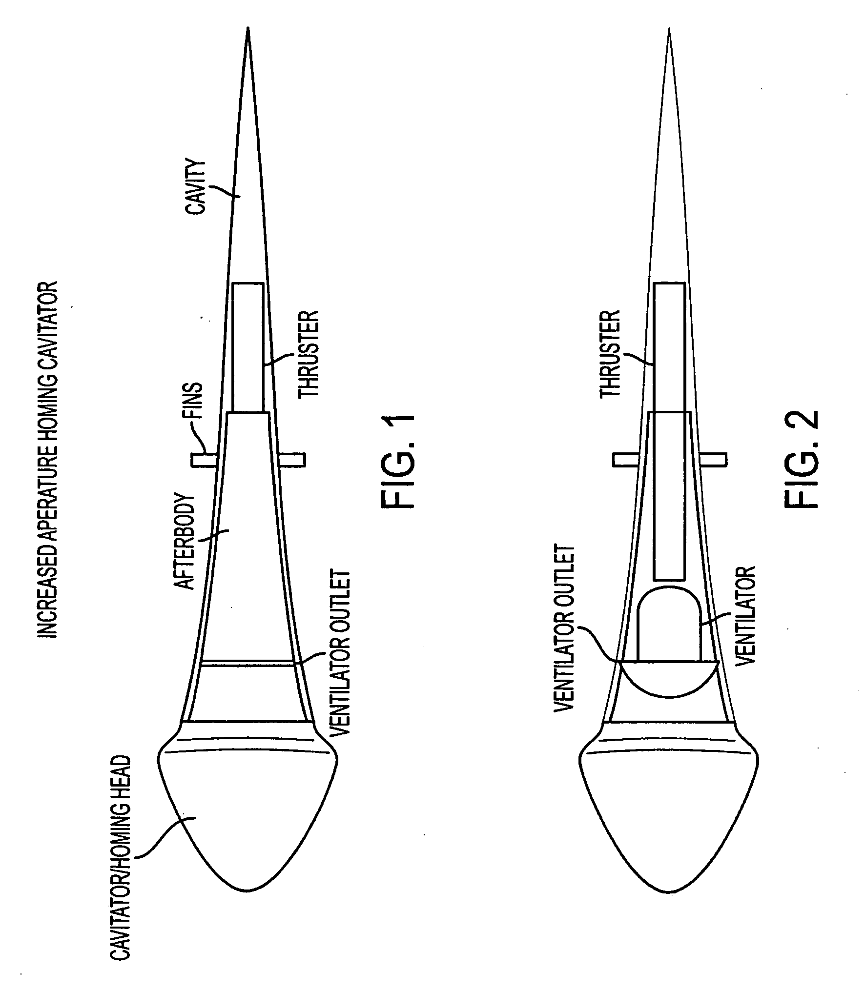
[0010] In an exemplary embodiment, the size of the cavitator may be increased without a significant attendant increase in drag, thereby enabling a homing array of increased size and aperture.

Problems solved by technology

However, the small wetted area of the cavitator poses problems if that area is to host transducers suitable for forming the elements of a sonar system.
Specifically, the amount of acoustical power that can be transmitted via the small wetted area is limited: overpowering the system causes cavitation on the nominally wetted transducer faces, causing severe performance degradation.
Furthermore, the aperture of the sonar array is limited by the small cavitator diameter.
Finally, the number of array elements that can be practically packed within such a small volume is also quite limited, which in turn limits the beam-forming capabilities of the system.
Since drag of such a cavitator is directly proportional to its sectional area at the plane of cavity detachment, simply increasing the cavitator size is not a practical option, since it would eliminate the drag advantage that is otherwise gained via supercavitation.

Method used


Image

  • Increased aperture homing cavitator
  • Increased aperture homing cavitator
  • Increased aperture homing cavitator

Examples


Embodiment Construction

[0018] An exemplary embodiment of the invention is discussed in detail below. While specific exemplary embodiments are discussed, it should be understood that this is done for illustration purposes only. A person skilled in the relevant art will recognize that other components and configurations can be used without parting from the spirit and scope of the invention.

[0019] An alternative cavitator design can generate a concave cavity that closes in a cusp. It is well known (see, for example, Batchelor, 1967; Lighthill, 1949; Nesteruk 2000-2004) that the cavitation number associated with a concave cavity is negative; that is, the cavity pressure is greater than ambient pressure. See for example, Nesteruk, I., (2002) “The Problems of Drag Reduction in High Speed Hydrodynamics,”Proceedings of the International Summer Scientific School on High-Speed Hydrodynamics (HSH2002), National Academy of Sciences and Art of Chuvash Republic, Cheboksary, Russia, inter alia, the contents of which ar...


PUM


Abstract

Various exemplary embodiments of an increased aperture homing cavitator are disclosed. In one exemplary embodiment, a supercavitating body may include, e.g., but may not be limited to, a cavitator assembly having a front end and a back end, and having a shape operative to generate a concave cavity; an acoustical homing array coupled to the cavitator assembly; an afterbody coupled to the back end; a thruster coupled to the afterbody; and a ventilation system disposed within the afterbody, operative to supply gas to, and to maintain pressure within the cavity. In an exemplary embodiment, the size of the cavitator may be increased without a significant attendant increase in drag, thereby enabling a homing array of increased size and aperture.

Description

RELATED APPLICATION [0001] This application claims the benefit under 35 U.S.C. Section 119(e) of U.S. application Ser. No. 60 / 651,624, filed Feb. 11, 2005, entitled “Increased Aperture Homing Cavitator,” to Kirschner et al., of common assignee, the contents of which are incorporated by reference in their entirety.BACKGROUND OF THE INVENTION [0002] 1. Field of the Invention [0003] The present invention relates generally to supercavitating high-speed bodies, and more particularly to supercavitating torpedoes. [0004] 2. Related Art [0005] Homing supercavitating torpedo concepts currently being considered in ongoing research and development programs employ cavitators with a positive pressure drag coefficient, which is well known to produce a concave cavity that expands outward in the downstream direction from the cavity inception point to some maximum cavity radius, then contract to the point of cavity closure, usually positioned downstream of the body. A significant drag advantage is o...

Claims


Application Information

Patent Timeline
IPC IPC(8): F24H1/10H05B3/78
CPCF42B10/46F42B19/005
Inventor KIRSCHNER, IVAN N.BULEY, GREG
Owner GEN DYNAMICS INFORMATION TECH
Why Eureka
Try Eureka