Injection molding machine

Inactive Publication Date: 2007-04-05
KONICA MINOLTA OPTO
View PDF28 Cites 5 Cited by
  • Summary
  • Abstract
  • Description
  • Claims
  • Application Information

AI Technical Summary

Benefits of technology

[0015] According to the inventive injection molding machine, an optical element is manufactured w

Problems solved by technology

If temperature is too low, molding accuracy deteriorates.
If temperature is too high, resin deteriorates or gets stringiness.
However, with the advance of accuracy of optical elements, temperature control accuracy managed by the conventional injection molding machine has become ins

Method used


Image

  • Injection molding machine
  • Injection molding machine
  • Injection molding machine

Examples


Embodiment Construction

[0020] Preferred embodiments of the present invention will be described in detail below with reference to the accompanying drawings. In this embodiment, the present invention is applied to a lens molding device for manufacturing a plurality of lenses of a camera to be installed in a portable terminal at once. The lens molding device of the present embodiment is to mold a small optical element of which outside diameter is 12 nm or smaller, and an optical element to be mold is required to keep accuracy such as Ra 20 nm or smaller surface roughness of its optical surface. The present embodiment is applied to micro injection molding devices of which clamping force is 150 kN or lower.

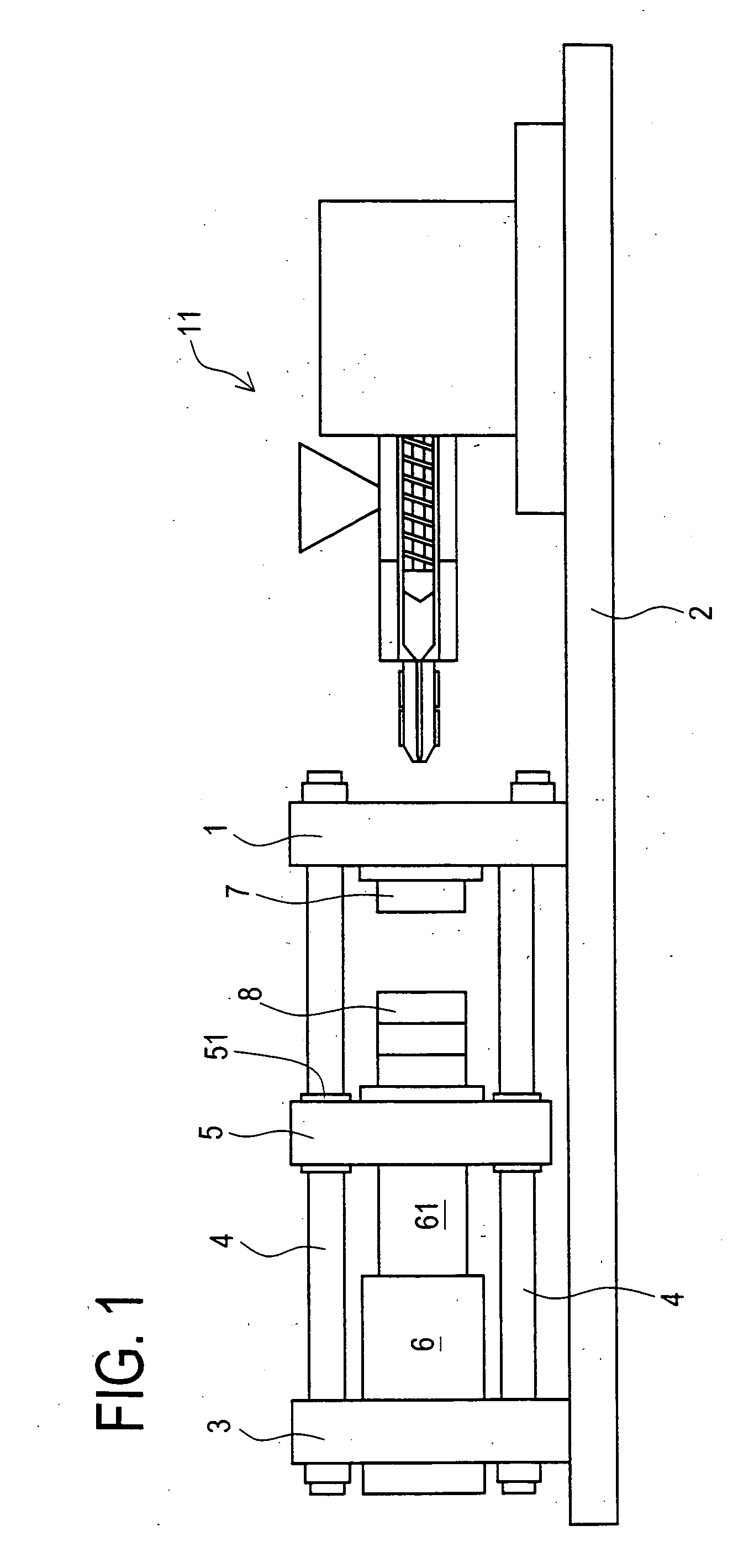
[0021] The lens molding device of the present embodiment is such structured as shown in FIG. 1. That is, a fixed platen 1 and a rear platen 3 are fixedly provided on a frame 2. Those platens 1 and 3 are substantially square shaped when looked from the left or right side with reference to FIG. 1. Four tie-ba...


PUM

PropertyMeasurementUnit
Diameteraaaaaaaaaa
Diameteraaaaaaaaaa
Temperatureaaaaaaaaaa

Abstract

An injection molding comprises: a fixed mold; a movable mold which is capable of contacting to and separating from the fixed mold; and an injection unit which supplies molten resin to a space formed between the fixed mold and the movable mold when being pressed to a non-molding face of the fixed mold. The injection unit comprises: a nozzle portion which injects molten resin to the space formed between the molds; an injecting portion which applies molten resin pressure toward the space formed between the fixed mold and the movable mold though the nozzle portion; a heater and a temperature sensor provided on the nozzle portion; and a heater and a temperature sensor provided on the injecting portion, and detection accuracy of the sensor of the nozzle portion is higher than that of the injecting potion. There is thus provided an injection molding machine capable of manufacturing optics with high accuracy without considerable cost-up by realizing stable and highly accurate injection.

Description

CROSS-REFERENCE TO RELATED APPLICATIONS [0001] This application is based upon and claims the benefit of priority from the prior Japanese Patent Application No. 2005-283045 filed on Sep. 28, 2005, the entire contents of which are incorporated herein by reference. BACKGROUND OF THE INVENTION [0002] 1. Field of the Invention [0003] The present invention relates to an injection molding machine for molding an optical element with a mold. More particularly, it relates to an injection molding machine which controls temperature with high accuracy to improve molding accuracy. [0004] 2. Description of the Related Art [0005] There have conventionally been manufactured various molded items by injection molding. For example, JP Unexamined Patent Publication No. 10-323872 discloses an injection molding machine for molding disks utilized as information recording media. FIG. 4 shows schematic structure of the molding injection machine directed to the Publication No. 10-323872. The molding injection...

Claims


Application Information

Patent Timeline
IPC IPC(8): B29C45/78B29C45/74
CPCB29C45/74B29C45/78B29C2045/2741B29C2045/2754B29L2011/00B29C2045/0094
Inventor MATSUMOTO, AKIHIKOOKUMURA, YOSHIHIROHARA, SHINICHIROSEKIHARA, KANJI
Owner KONICA MINOLTA OPTO
Why Eureka
Try Eureka