Optical recording medium, method for reproducing information and optical information reproducing apparatus

Inactive Publication Date: 2007-04-05
KK TOSHIBA
View PDF6 Cites 16 Cited by
  • Summary
  • Abstract
  • Description
  • Claims
  • Application Information

AI Technical Summary

Benefits of technology

[0009] The invention has been made under these circumstances and provides an optical recording medium having information layers, a method for reproducing optical information and an optical information reproducing apparatus, which are effective in reproducing information recorded in a selected reproduction layer independently with high accuracy without interference with another information layer not selected at the time of reproduction.
[0013] According to the above configuration, information recoded in a selected reproduction layer can be reproduced independently with high accuracy without interference with another information layer not selected at the time of reproduction even in the case where the number of information layers including recording layers respectively is increased. It is possible to provide an optical recording medium with a large recording capacity without crosstalk between a reproduction layer and a non-reproduction layer.

Problems solved by technology

For this reason, this reflected light component may become noise in a reflected light component from the reproduction layer, so that S / N is worsened.
As a result, the error rate of a reproduction signal cannot be reduced sufficiently.

Method used


Image

  • Optical recording medium, method for reproducing information and optical information reproducing apparatus
  • Optical recording medium, method for reproducing information and optical information reproducing apparatus
  • Optical recording medium, method for reproducing information and optical information reproducing apparatus

Examples


first embodiment

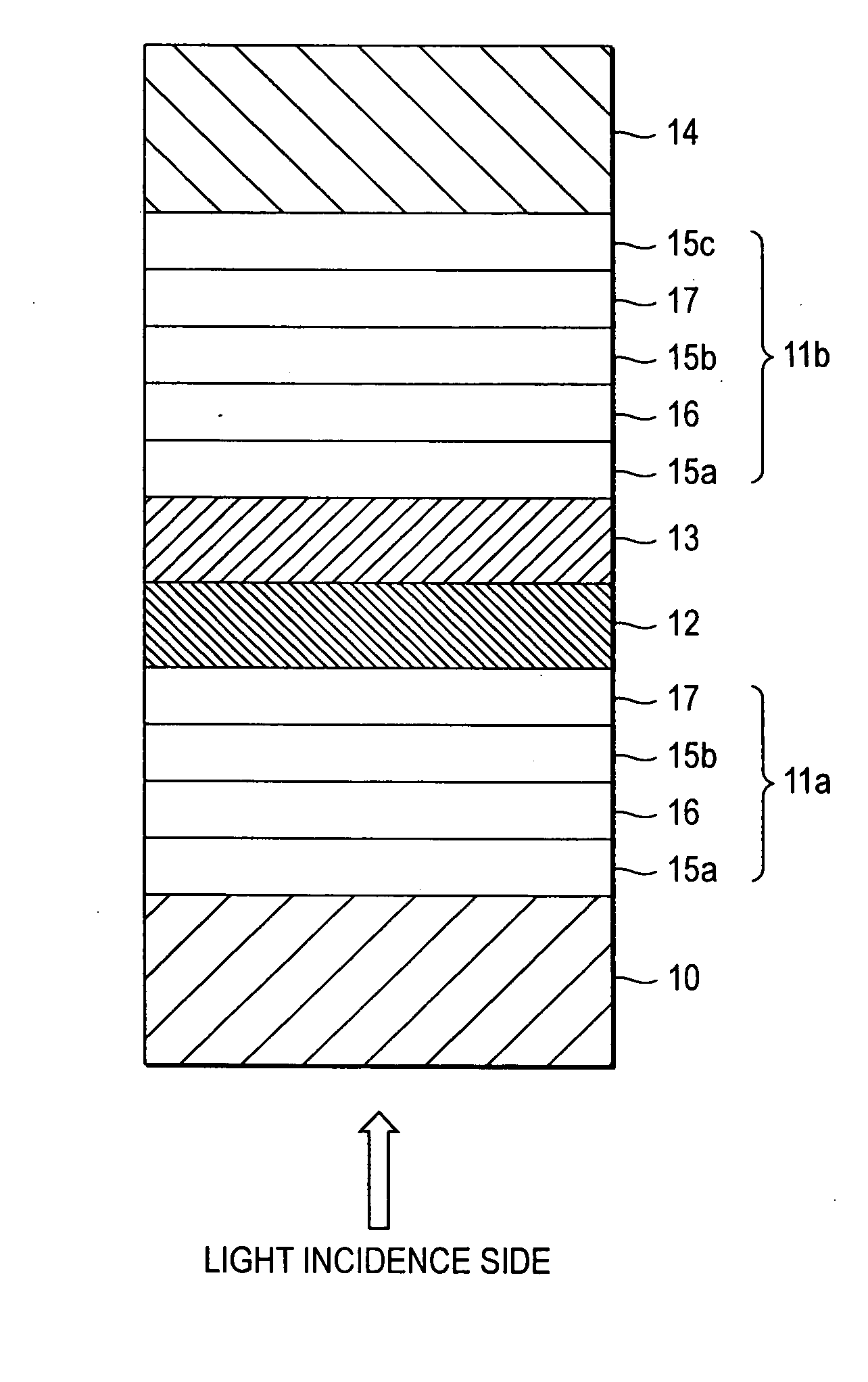
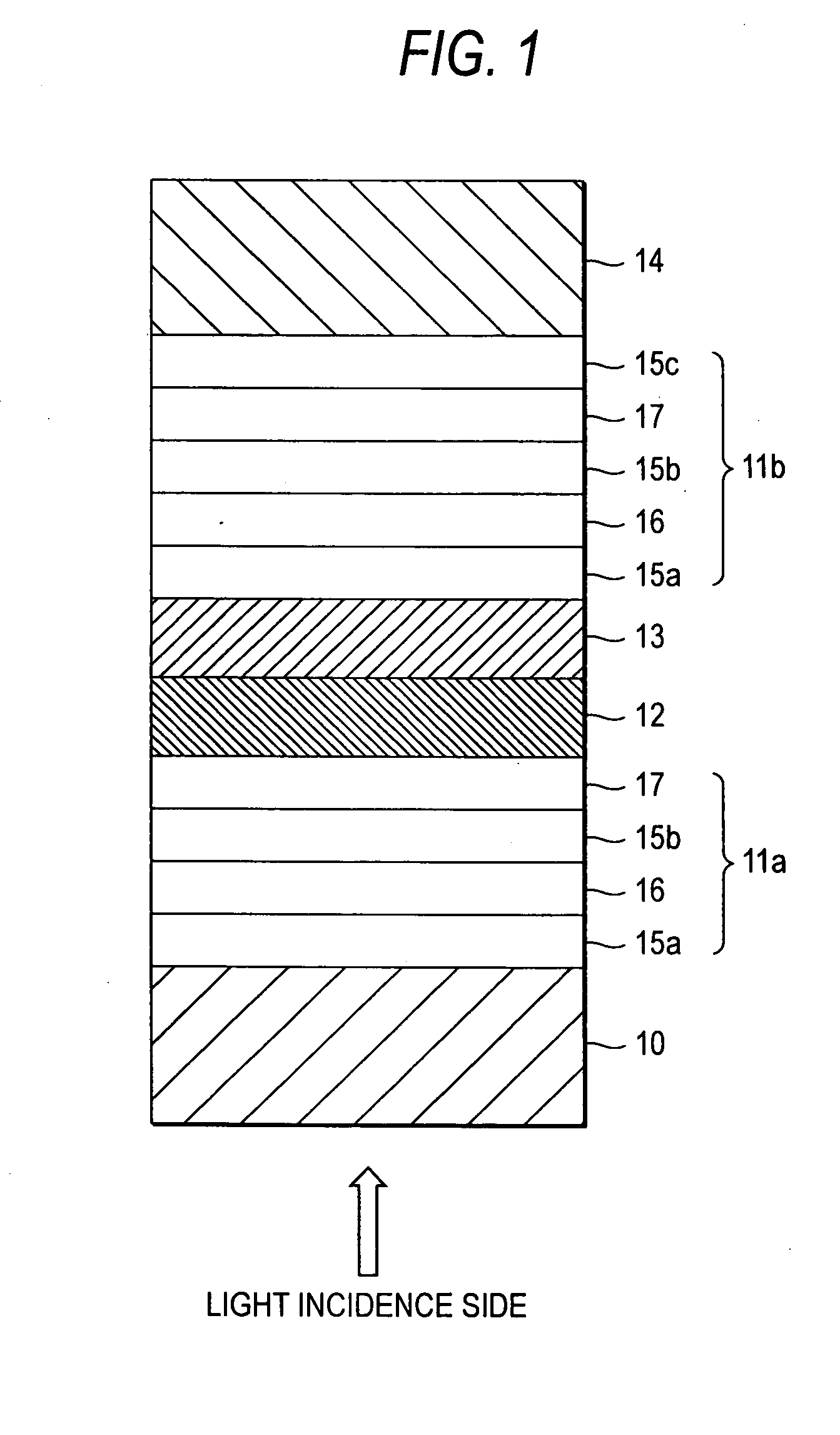
[0032] As shown in FIG. 1, an optical recording medium according to a first embodiment of the invention is formed as a single-side double-layer rewritable optical recording medium which includes a first substrate 10, a first information layer 11a, an absorption variation layer 12, an intermediate layer 13, a second information layer 11b and a second substrate 14 laminated successively when viewed from a light incidence side. The first information layer 11a has a protective layer 15a, a recording layer 16, a protective layer 15b and a reflection layer 17 laminated successively when viewed from the light incidence side. The second information layer 11b has a protective layer 15a, a recording layer 16, a protective layer 15b, a reflection layer 17 and a protective layer 15c laminated successively when viewed from the light incidence side.

[0033] The first substrate 10 is made of a material which is transparent to the wavelength of reproduction light so as not to disturb incidence of li...

example 1

Single-Side Double-Layer Rewritable Medium

[0055] After a 30 nm-thick ZnS—SiO2 film was formed as an optical interference layer 101a on a 0.6 mm-thick polycarbonate substrate (hereinafter referred to as “first substrate”) 100 having 50 nm-deep grooves arranged at intervals of a track pitch of 0.37 μm by RF magnetron sputtering with 1 kW, a 10 nm-thick Ge40Sb4Te52Bi4 film was formed as a recording layer 102 by RF magnetron sputtering with 0.2 kW. After a 10 nm-thick ZnS—SiO2 film was then formed as an optical interference layer 101b by RF magnetron sputtering with 1 kW, a 10 nm-thick Ag98Pd1Cu1 film was formed as a reflection layer 103 by DC magnetron sputtering with 1 kW. Thus, a first information layer 104 was formed on the first substrate 100.

[0056] Then, a 200 nm-thick film of ZnO which was a thermochromic material was formed as an absorption variation layer 105 on the first information layer 104 by RF magnetron sputtering with 1 kW.

[0057] On the other hand, after a 30 nm-thick...

example 2

Single-Side Double-Layer Rewritable Medium

[0060] A first information layer 104 was formed on a first substrate 100 by use of the same material and method as those in Example 1.

[0061] Then, a 100 nm-thick ZnSe film of a saturable absorption material with a forbidden band width of 2.8 eV (equivalent to 440 nm) was formed as an absorption variation layer 105 on the first substrate 104 by binary simultaneous RF magnetron sputtering of a ZnSe target and a SiO2 target in Ar gas with a substrate bias applied for controlling the particle size of ZnSe particles.

[0062] The absorption variation layer 105 formed thus was formed so that 50% by volume of ZnSe fine particles with a mean particle size of 5 nm were dispersed in SiO2. The forbidden band width was slightly widened because ZnSe was provided as fine particles, so that the forbidden band width became 3.1 eV equivalent to energy of light with 405 nm substantially equal to the wavelength of reproduction light. The rising time of the sat...


PUM


Abstract

An optical recording medium includes a plurality of information layers and an absorption variation layer. Information is recorded in the plurality of information layers. The absorption variation layer is disposed between respective two adjacent information layers. Light transmittance of each absorption variation layer varies in accordance with light applied thereto.

Description

CROSS-REFERENCE TO RELATED APPLICATIONS [0001] This application is based upon and claims the benefit of priority from the Japanese Patent Application No.2005-285589 filed on Sep. 29, 2005; the entire contents of which are incorporated herein by reference. BACKGROUND OF THE INVENTION [0002] 1. Field of the Invention [0003] The present invention relates to an optical recording medium, an optical information reproducing method and an optical information reproducing apparatus, in which information can be recorded and reproduced when light is applied onto the optical recording medium. [0004] 2. Description of the Related Art [0005] Optical recording media such as a CD and a DVD have become widespread as data storage media for storing audio data, image data, motion image data, etc. The optical recording media have been put into practice use as read-only media and rewritable media. A multilayer recording medium having recording layers has been proposed as a measure to improve the recording...

Claims


Application Information

Patent Timeline
IPC IPC(8): G11B7/24G11B7/2403G11B7/24038
CPCG11B7/2403G11B7/24038G11B7/246G11B7/252G11B7/2533G11B7/2534G11B7/2535G11B7/259G11B2007/24312G11B2007/24314G11B2007/24316G11B2007/25706G11B2007/25708G11B2007/2571G11B2007/25711G11B2007/25713G11B2007/25715G11B2007/25716
Inventor SATOH, YASUHIROASHIDA, SUMIOHIRONO, MASATOSHI
Owner KK TOSHIBA
Why Eureka
Try Eureka