Navigation system and vehicle position estimating method

a technology of navigation system and vehicle position, applied in navigation instruments, steering initiations, instruments, etc., can solve the problems of small estimation error of vehicle position, inability to correct, and accumulation of errors, so as to achieve more accurate estimation and estimate.

Inactive Publication Date: 2007-04-05
ALPINE ELECTRONICS INC
View PDF17 Cites 42 Cited by
  • Summary
  • Abstract
  • Description
  • Claims
  • Application Information

AI Technical Summary

Benefits of technology

[0059] According to the present invention, a sensor to detect a velocity and an azimuth of a vehicle is provided, a turning radius of the vehicle is calculated by using a signal output from the sensor, and a vehicle position is estimated on a road by using the turning radius. Accordingly, a vehicle position can be estimated more accurately when the vehicle is traveling around a curve by using a method different from that used when the vehicle is traveling straight.
[0060] According to the present invention, a vehicle position is estimated by determining that the vehicle is traveling straight when the angular velocity is equal to or smaller than a set value and by determining that the vehicle is traveling around a curve when the angular velocity is larger than the set value.

Problems solved by technology

In the SCN, however, errors accumulate as the vehicle runs, and thus an estimated vehicle position may deviate from a road.
In this method, an estimation error of a vehicle position is small when an actual road extends straight or substantially straight.
In an actual case, however, correction cannot be done and a result shown in FIG. 25A is generated.
In this method, however, the vehicle position cannot immediately be corrected and thus a time period during which the vehicle position deviates from the road becomes long.
However, such a vehicle position estimating method has not bee

Method used


Image

  • Navigation system and vehicle position estimating method
  • Navigation system and vehicle position estimating method
  • Navigation system and vehicle position estimating method

Examples


first embodiment

(a) Principle of Estimation of a Vehicle Position

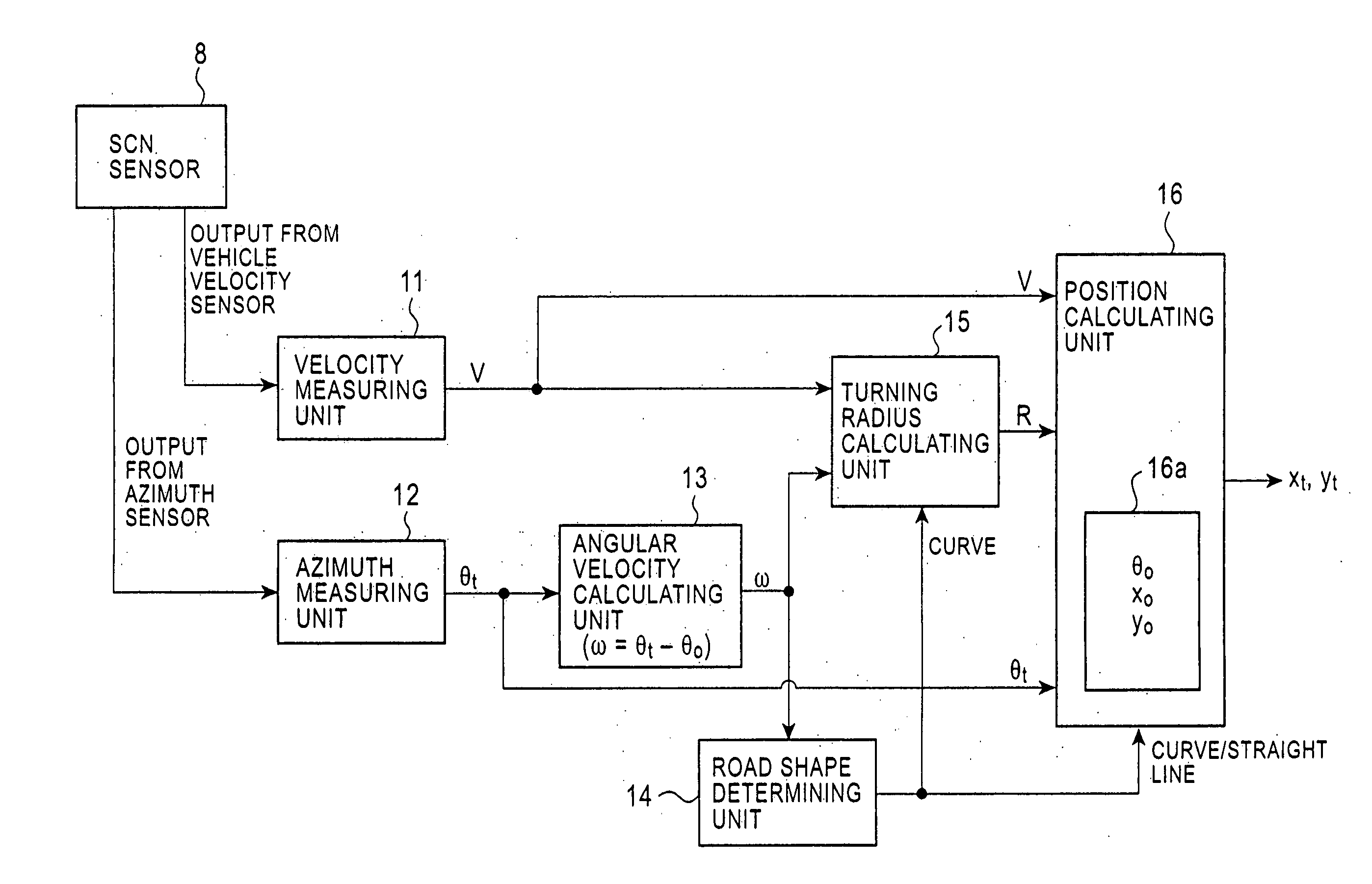
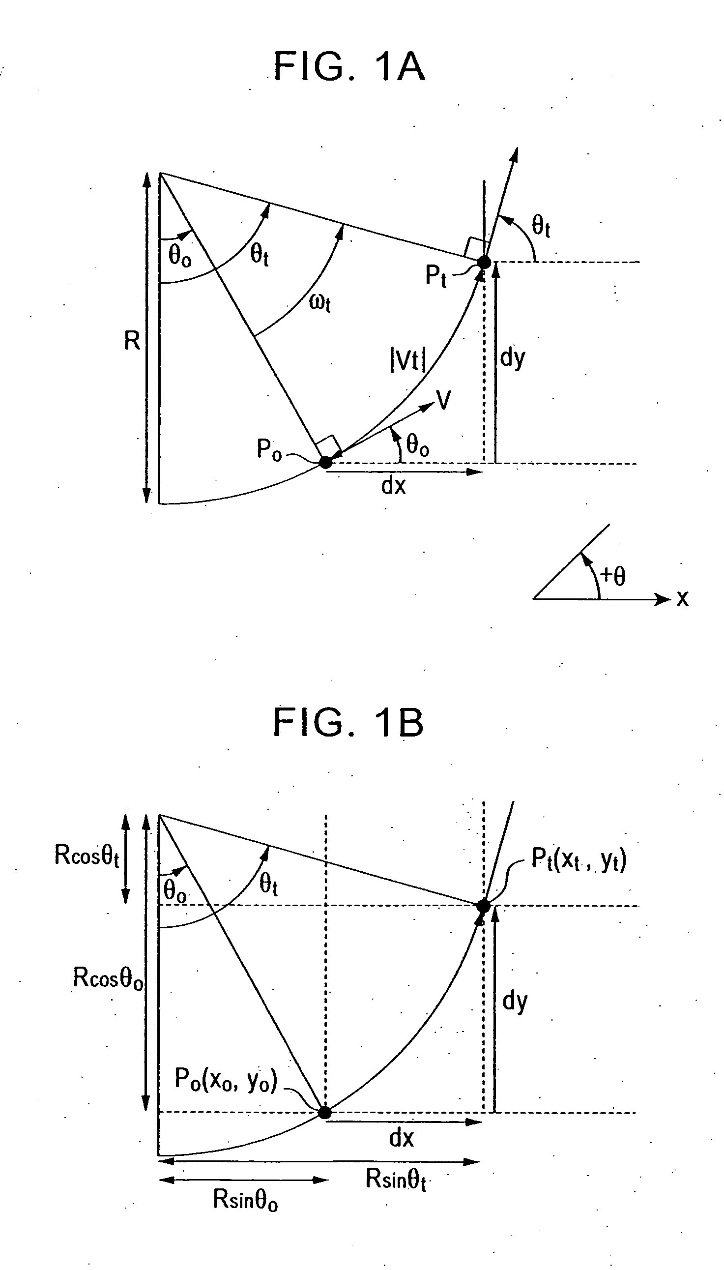
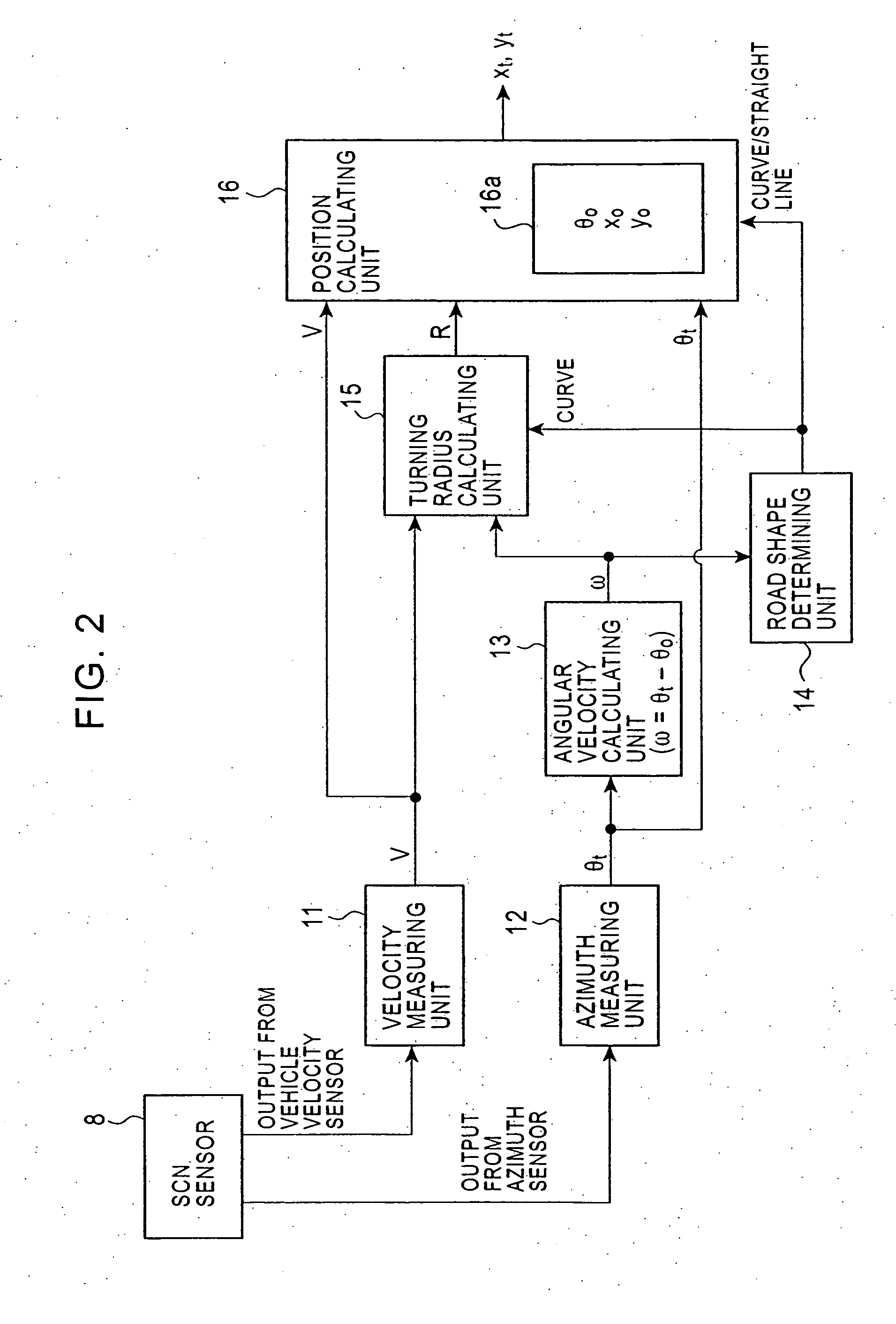
[0089] When a vehicle is traveling straight, a vehicle position is estimated on a straight road link by using the known method (see FIG. 18). However, when the vehicle is traveling around a curve, a turning radius R of the vehicle is calculated and a vehicle position is estimated on a curved road link having the radius R. FIGS. 1A and 1B are illustrations of a vehicle position estimating method used when the vehicle is traveling around a curve. The symbols shown in the figures represent the following:

[0090] R: turning radius of vehicle [m];

[0091] V: travel velocity of vehicle [m / sec];

[0092]ω: angular velocity of vehicle [radians / sec];

[0093] P0 (x0, y0): present position of vehicle;

[0094]θ0: present traveling direction of vehicle;

[0095] Pt (xt, yt): vehicle position after t seconds; and

[0096]θt (xt, yt): traveling direction of vehicle after t seconds.

[0097] Referring to FIG. 1A, the turning radius R of the vehicle when the ve...

second embodiment

[0116] A road link included in the map data is generated based on a center line of the road, and thus the road link on the map indicates the center line of the road. On the other hand, the estimated vehicle position in the first embodiment is a position on a line on which the vehicle actually travels. Thus, if the traveling line matches the center line of the road, the position on the center line of the road can be estimated even if the road is curved as shown in FIG. 5, and a vehicle position mark can be displayed on the road link in a drawn map. However, in Japan, for example, the vehicle does not actually travel on the center line but travels on a left side of the center line by a predetermined distance D. In other words, an actual turning radius of the vehicle is different than the radius of the road link. Therefore, a distance error occurs in the forward and backward directions on a curve and an estimated vehicle position deviates from the road link. FIG. 6 illustrates a situat...

third embodiment

[0154] A typical navigation system is designed on the assumption that only one vehicle position is to be estimated. That is, a position on a road link obtained by map matching a vehicle position estimated by using an SCN sensor is regarded as a vehicle position. By using the vehicle position on the road link, a vehicle position mark can be displayed on the road link on a map, a distance along the road can be calculated, and route guiding can be performed. However, with this vehicle position on the road link, a vehicle position mark cannot accurately be displayed at an actual vehicle position on a road on a town map, which accurately shows even a road width. Furthermore, an actual traffic lane cannot be estimated.

[0155] In the third embodiment, a first vehicle position corrected onto a road link (road center line) and a second vehicle position on an actual traveling line are constantly calculated and managed, and a process suitable for navigation control is performed by using one of...


PUM


Abstract

A turning direction calculating unit determines a turning direction of a vehicle based on a change in azimuth of the vehicle. An angular velocity calculating unit calculates an angular velocity of the vehicle. A turning radius calculating unit calculates a turning radius of the vehicle by using the angular velocity and a travel distance of each predetermined time period. A turning radius correcting unit corrects the turning radius so that the turning radius becomes larger by a correction value WL according to a traveling position on a road if the vehicle turns to the left, and corrects the turning radius so that the turning radius becomes smaller by a correction value WR according to a traveling position on a road if the vehicle turns to the right. A vehicle position estimating unit estimates a vehicle position on a center line of the road by using the corrected turning radius.

Description

RELATED APPLICATIONS [0001] The present application claims priority to Japanese Patent Application Number 2005-286755, filed Sep. 30, 2005, the entirety of which is hereby incorporated by reference. BACKGROUND OF THE INVENTION [0002] 1. Field of the Invention [0003] The present invention relates to a navigation system and a vehicle position estimating method. Particularly, the present invention relates to a navigation system and a vehicle position estimating method for accurately estimating a position of a vehicle by using signals output from a self-contained navigation (SCN) sensor. [0004] 2. Description of the Related Art [0005] In a navigation system, map data corresponding to a present position of a vehicle is read from a map data storing unit, such as a DVD (digital versatile disc) or an HDD (hard disk drive), and is displayed on a display. A vehicle position mark is moved on the map in accordance with the travel of the vehicle, or the vehicle position mark is fixed at a certai...

Claims


Application Information

Patent Timeline
IPC IPC(8): G01C21/00
CPCG01C21/00G01C21/12G01C21/3878
Inventor MORI, DAISHI
Owner ALPINE ELECTRONICS INC
Why Eureka
Try Eureka