
System and method of collision avoidance using an invarient set based on vehicle states and dynamic characteristics

a collision avoidance and invariant set technology, applied in the field of collision avoidance systems, can solve the problems of greater collision danger in flight formation, infinite maneuverability of straying vehicles, and greater collision potential

Inactive Publication Date: 2007-04-05
HONEYWELL INT INC
View PDF9 Cites 75 Cited by
  • Summary
  • Abstract
  • Description
  • Claims
  • Application Information

AI Technical Summary

Benefits of technology

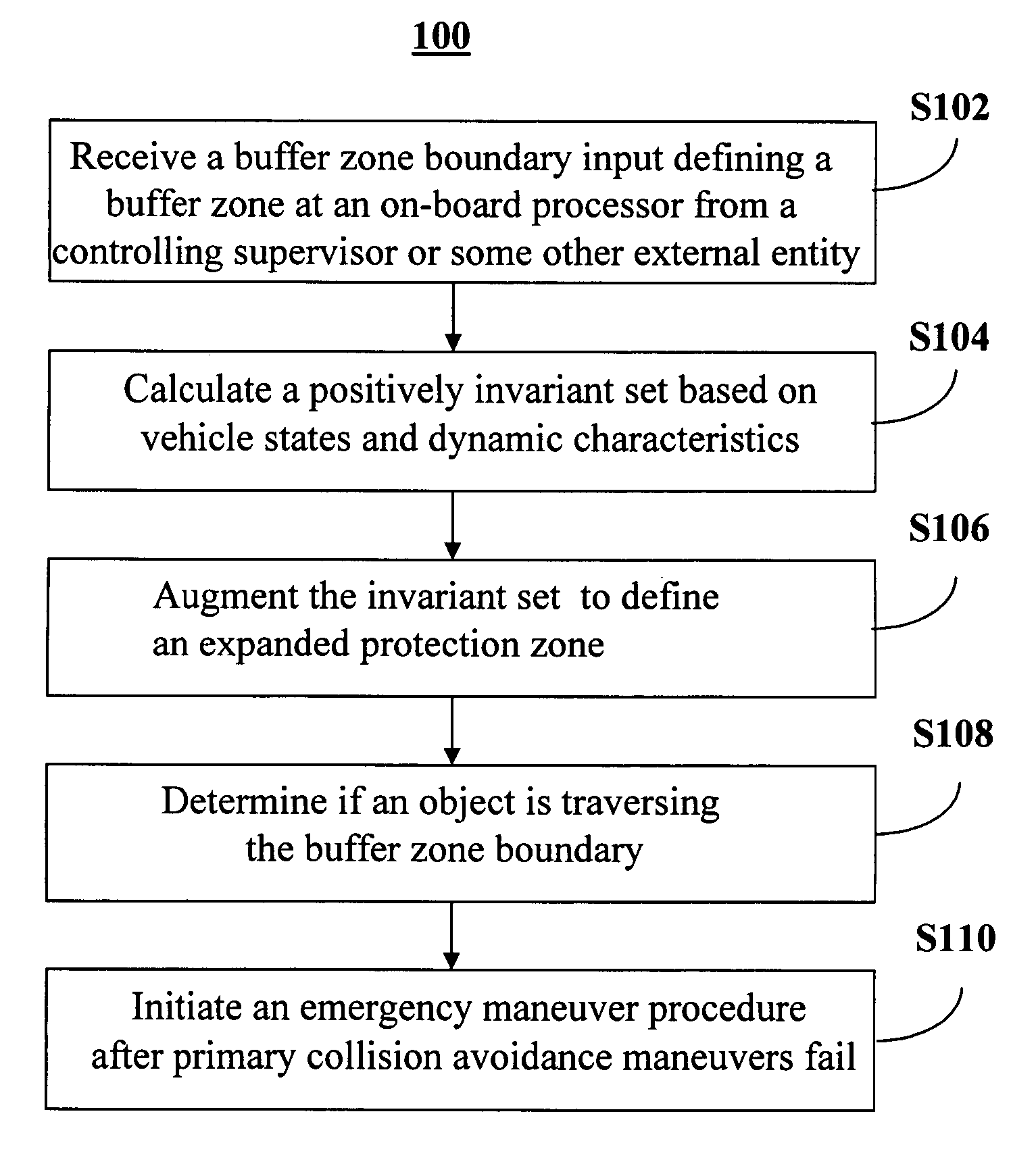
[0007] One aspect of the present invention provides a method to provide and implement a collision avoidance system for a vehicle. The method includes receiving a buffer zone boundary input defining a buffer zone at an on-board processor in the vehicle from a controlling supervisor. The method also includes calculating a positively invariant set based on vehicle states and dynamic characteristics. The positively invariant set defines a protection zone that is enclosed within the buffer zone and centered about the vehicle. The method also includes determining if an object is traversing the buffer zone boundary and initiating an emergency maneuver procedure after a primary collision avoidance maneuvers fail. The outcome is that the object does not enter the protection zone due to the emergency maneuver.
[0008] Another aspect of the present invention provides a collision avoidance system for a vehicle. The system includes an external processor, an on-board processor, a vehicle controller and sensors. The external processor is operable to compute a positively invariant set based on a vehicle states and dynamic characteristics and to up-load the positively invariant set to the on-board processor. The positively invariant set defines a protection zone. The on-board processor is operable to receive the positively invariant set from the external processor and to store data defining a buffer zone boundary of the vehicle, wherein the protection zone is enclosed within the buffer zone boundary. The vehicle controller and sensors are in communication with the on-board processor. The sensors detect objects within the buffer zone boundary. T

Problems solved by technology

When vehicles are traveling in flight formation, the potential for collisions is greater than that for vehicles traveling solo or at a great distance from other vehicles.
The higher the speed of the vehicles in the flight formation, the greater the danger of collision in the flight formation in the event that one vehicle strays from the intended flight path of the flight formation.
The collision avoidance constraints assume the straying vehicle has infinite maneuverability, since they do not take into account real-world limitations in actuation authority, acceleration and velocity for the straying vehicle.
Since no vehicles have infinite maneuverability, such collision avoidance systems are not failure-proof.
UAVs that go down, owing to collision, pose a risk to the safety of the soldiers who depend on the UAV.
If the solders do not receive the necessary information from a scouting UAV, they will be more vulnerable in the battlefield.
Additionally, the soldiers are placed at higher risk if classified data from a downed UAV is obtained by the enemy.
Moreover, autonomous UAVs that either have no collision avoidance systems or are only equipped with (failure-prone) primary collision avoidance systems pose a significant hazard to other manned vehicles operating in the same air space.
Any effort to generate collision-free paths for teams of vehicles on-the-fly in a centralized manner would require rapid solutions to large, non-convex optimization problems which places a significant computational burden on the centralized controller / planner and presents a single point of failure for the whole system.
This problem grows with the number of vehicles.
Although decentralized control / planning techniques hold great promise for generating collision-free paths that do not have the short-comings identified above, they provide no collision avoidance guarantees.

Method used


Image

  • System and method of collision avoidance using an invarient set based on vehicle states and dynamic characteristics
  • System and method of collision avoidance using an invarient set based on vehicle states and dynamic characteristics
  • System and method of collision avoidance using an invarient set based on vehicle states and dynamic characteristics

Examples


first embodiment

[0069]FIG. 5 is a schematic diagram of zones for a vehicle 105 having a collision avoidance system 10 in accordance with the present invention. The vehicle 105 is at the center of a buffer zone boundary 110 which encloses buffer zone 115. The vehicle's protection zone 125 has a protection zone boundary 120 that is concentric with and enclosed within the buffer zone boundary 110.

second embodiment

[0070] The discussion related to FIGS. 6-9D is based on the exemplary vehicle 100 and vehicle 200 of FIG. 4 in collision avoidance system 10. FIG. 6 is a schematic diagram of zones for a vehicle 100 operable in the collision avoidance system 10 in accordance with the present invention. In this embodiment, the vehicle 100 has the buffer zone 115 and protection zone 125 as described above for vehicle 105 and an additional expanded protection zone 135, that is enclosed within the buffer zone 115 and that encompasses the protection zone 125. The expanded protection zone boundary 130 that defines the limits of the expanded protection zone 135 is concentric with the buffer zone boundary 110 and the protection zone boundary 120.

[0071]FIGS. 7A-7D are schematic diagrams of the vehicle 100 of FIG. 6 initially on a collision path with an object 140 at various times during an implementation of the collision avoidance system 10 in accordance with one embodiment of the present invention. FIG. 7A ...


PUM


Abstract

A method to provide and implement a collision avoidance system for a vehicle. The method includes receiving a buffer zone boundary input defining a buffer zone at an on-board processor in the vehicle from a controlling supervisor, calculating a positively invariant set based on vehicle states and dynamic characteristics, the positively invariant set operable to define a protection zone enclosed within the buffer zone and centered about the vehicle, determining an object is traversing the buffer zone boundary; and implementing an emergency maneuver procedure after a collision avoidance maneuver fails, wherein the object does not enter the protection zone.

Description

TECHNICAL FIELD [0001] The present invention relates to collision avoidance systems and in particular to a collision avoidance system including emergency maneuvers in the event that collision avoidance maneuvers fail. BACKGROUND [0002] When vehicles are traveling in flight formation, the potential for collisions is greater than that for vehicles traveling solo or at a great distance from other vehicles. The higher the speed of the vehicles in the flight formation, the greater the danger of collision in the flight formation in the event that one vehicle strays from the intended flight path of the flight formation. Thus, vehicles traveling in a flight formation typically include collision avoidance systems of one form or another. For many autonomous vehicle applications, envisaged collision avoidance systems use collision avoidance constraints, which are translated into a minimization of the barrier functions or potential functions when a vehicle travels in a direction leading to coll...

Claims


Application Information

Patent Timeline
IPC IPC(8): G08G1/16G01S13/933
CPCG01S13/9303G08G5/0021G08G5/045G05D1/104G01S13/933
Inventor FREGENE, KINGSLEY O.C.BORELLI, FRANCESCOSUBRAMANIAN, DHARMASHANKAR
Owner HONEYWELL INT INC
Learn More