
Contact shape computing apparatus and method, and computer program therefor

a computing apparatus and a technology for contact shapes, applied in computing, digital computers, instruments, etc., can solve problems such as inconvenience, difficult to achieve satisfactory simulation, and inability to completely compute contact polygons, and achieve fast dynamic simulation, fast computation, and fast

Inactive Publication Date: 2007-04-05
SONY CORP
View PDF6 Cites 23 Cited by
  • Summary
  • Abstract
  • Description
  • Claims
  • Application Information

AI Technical Summary

Benefits of technology

[0016] It is also desirable to provide a satisfactory contact shape computing apparatus and method and a computer program therefor for completely and quickly computing a contact polygon between two solid bodies in collision or in contact with each other.
[0036] According to the embodiments of the present invention, an accurate ground polygon can be quickly computed by conducting only a local search based on a pair of collision representative points (the most penetrating points or the closest points) obtained with a collision detection algorithm. Using the computed ground polygon, a fast dynamic simulation can be performed or legged mobile robots can be controlled in a more complex environment.

Problems solved by technology

However, many of the known collision detection algorithms can obtain only some of the collision points between two solid bodies and are unable to completely compute the contact polygon.
Inconvenience is caused when a dynamic simulation is performed directly using the result of an insufficient collision detection algorithm.
It is thus difficult to achieve satisfactory simulation results.
However, all of the above methods perform calculations using all the vertices of two solid bodies interfering with each other, thus involving a large number of calculations.
If the shape becomes more complex or the number of objects increases, it may be difficult to perform a simulation in real time.

Method used


Image

  • Contact shape computing apparatus and method, and computer program therefor
  • Contact shape computing apparatus and method, and computer program therefor
  • Contact shape computing apparatus and method, and computer program therefor

Examples


Embodiment Construction

[0062] Embodiments of the present invention will be described in detail with reference to the drawings.

A. Method of Computing Contact Polygon

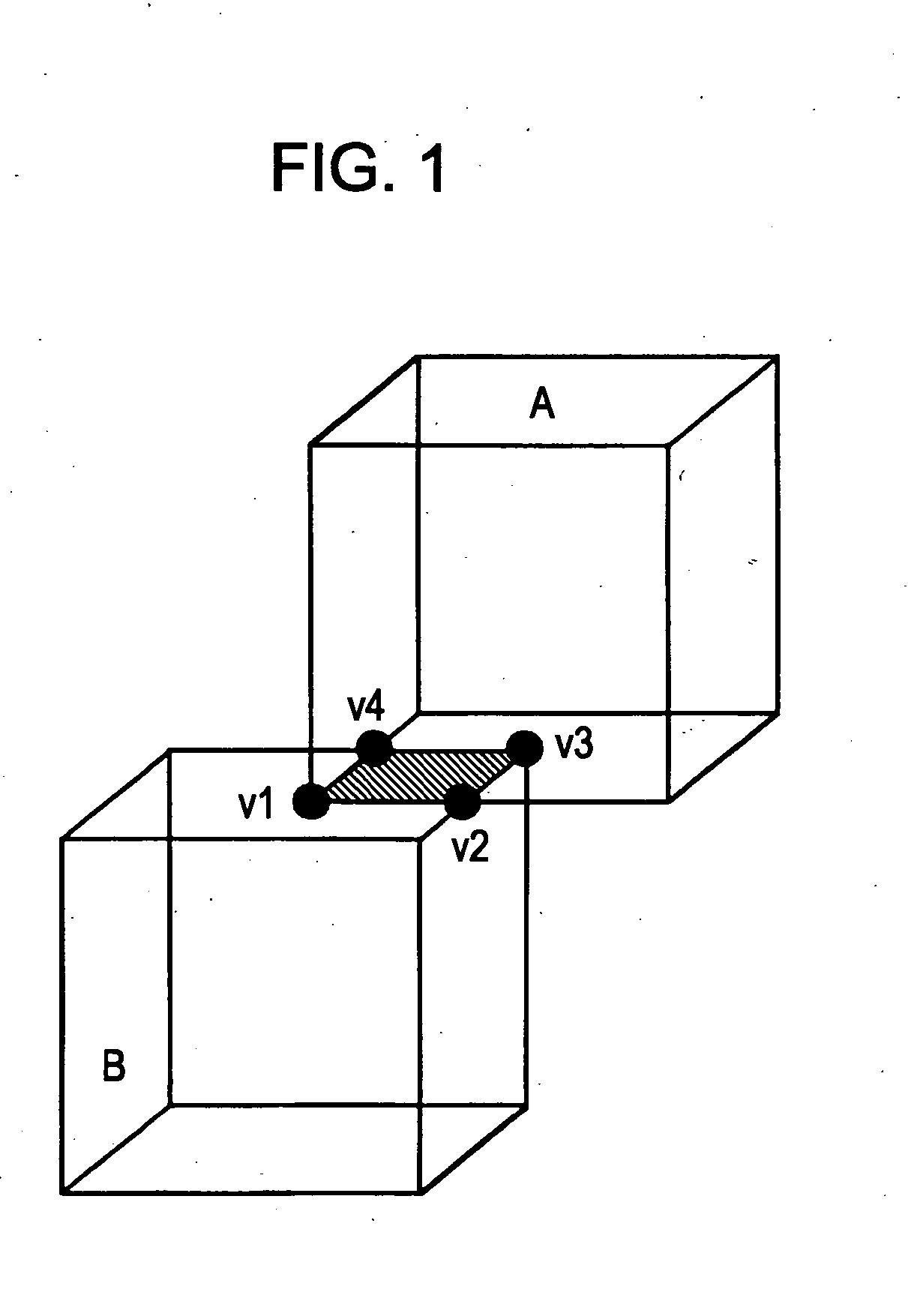
[0063] The present invention relates to a contact polygon computing method of quickly computing a contact polygon between convex solid bodies in collision or in contact with each other. For the sake of simplification, as shown in FIG. 1, in the case where two cubes A and B are interfering with each other, a method of computing a contact polygon (v1, v2, v3, and v4) will be described by way of example.

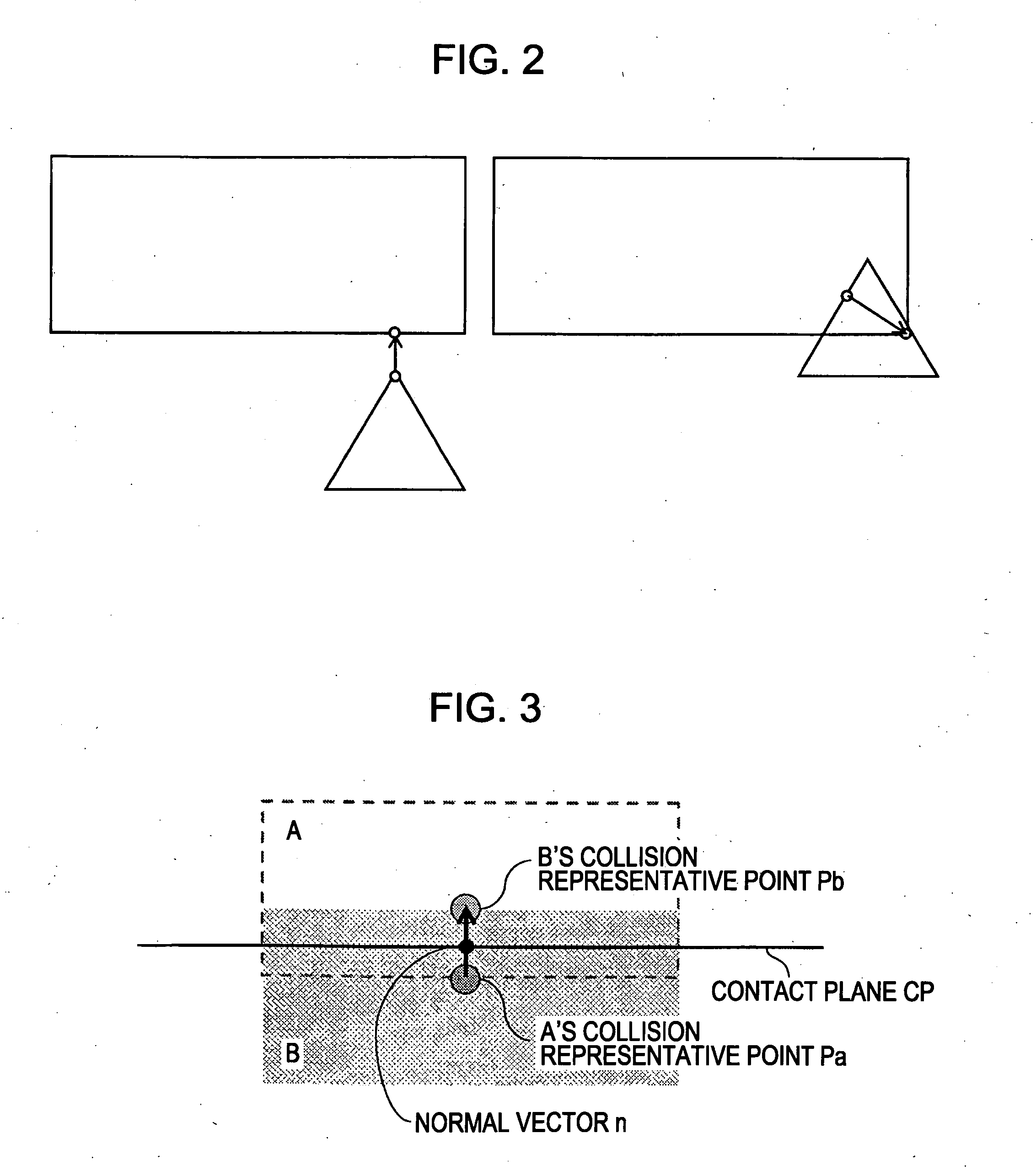
[0064] According to an embodiment of the present invention, known collision detection algorithms are applicable for detecting contact between solid bodies. It is assumed that the Gilbert-Johnson-Keerthi distance algorithm (abbreviated as “GJK”) is used here as the collision detection algorithm. The GJK is an iterative method of computing the distance between convex figures. As shown in FIG. 2, the GJK algorithm involves obtaining a set of colli...


PUM


Abstract

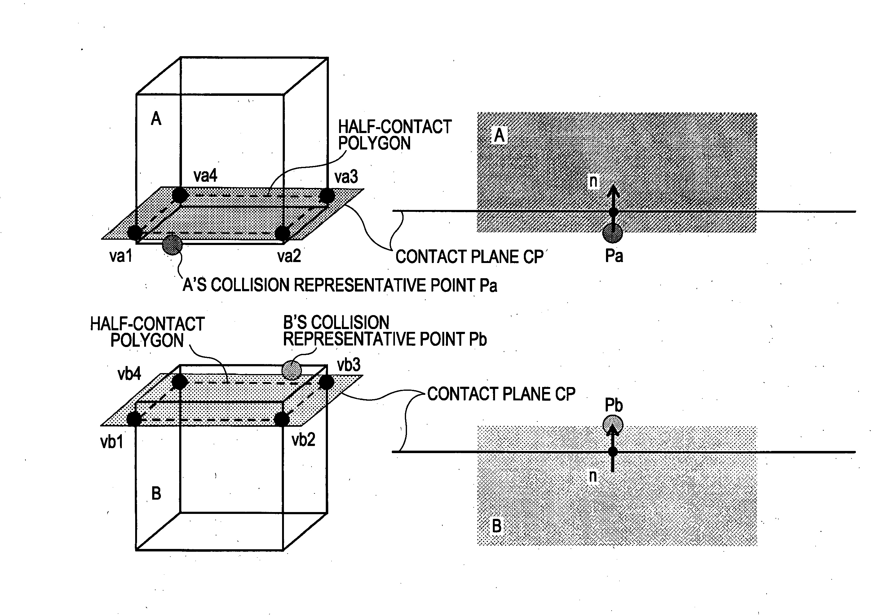
A contact shape computing apparatus for detecting contact between a plurality of three-dimensional solid models and computing a contact shape between two solid bodies in contact with each other includes the following elements: a collision detector operable to detect a collision or contact between the two solid bodies; a contact plane setting unit operable to define a contact plane that passes through a common region of the two solid bodies; a contact problem solving unit operable to individually solve contact states of the solid bodies with the contact plane as half-contact problems; and a contact shape computing unit operable to compute the contact shape between the two solid bodies by uniting solutions of the half-contact problems for the associated solid bodies, the solutions being obtained by the contact problem solving unit.

Description

CROSS REFERENCES TO RELATED APPLICATIONS [0001] The present invention contains subject matter related to Japanese Patent Application JP 2005-289598 filed in the Japanese Patent Office on Oct. 3, 2005, the entire contents of which are incorporated herein by reference. BACKGROUND OF THE INVENTION [0002] 1. Field of the Invention [0003] The present invention relates to contact shape computing apparatuses and methods and computer programs therefor for detecting contact between a plurality of three-dimensional solid models and computing a contact shape between two solid bodies in contact with each other. More particularly, the present invention relates to a contact shape computing apparatus and method and a computer program therefor for completely and quickly computing a contact polygon between two solid bodies in collision or in contact with each other. [0004] 2. Description of the Related Art [0005] Recently, research and development of the structure and stable walking control of legge...

Claims


Application Information

Patent Timeline
Patent Type & Authority Applications(United States)
IPC IPC(8): G06F15/00
CPCG06T17/10G06T19/00G06T2210/21G06T2219/008
Inventor NAGASAKA, KENICHIRONAGANO, MASAKUNI
Owner SONY CORP
Learn More