Accelerated occlusion culling using directional discretized occluders and system therefore

Inactive Publication Date: 2003-06-03
IBM CORP
View PDF7 Cites 33 Cited by
  • Summary
  • Abstract
  • Description
  • Claims
  • Application Information

AI Technical Summary

Problems solved by technology

Interactive visualization of these large polygonal models, places an enormous burden upon the current graphics hardware and makes image rendering very complex and time consuming.
This complexity makes it impossible to render at interactive rates with state of the art hardware, especially when interactively rendering large 3D models and is a well known problem in the art.
Unfortunately, the Teller & Sequin approach has been presented, typically, within a framework of architectural models wherein cells (e.g., floors, rooms, hallways) and portals (e.g., door

Method used


Image

  • Accelerated occlusion culling using directional discretized occluders and system therefore
  • Accelerated occlusion culling using directional discretized occluders and system therefore
  • Accelerated occlusion culling using directional discretized occluders and system therefore

Examples


Example

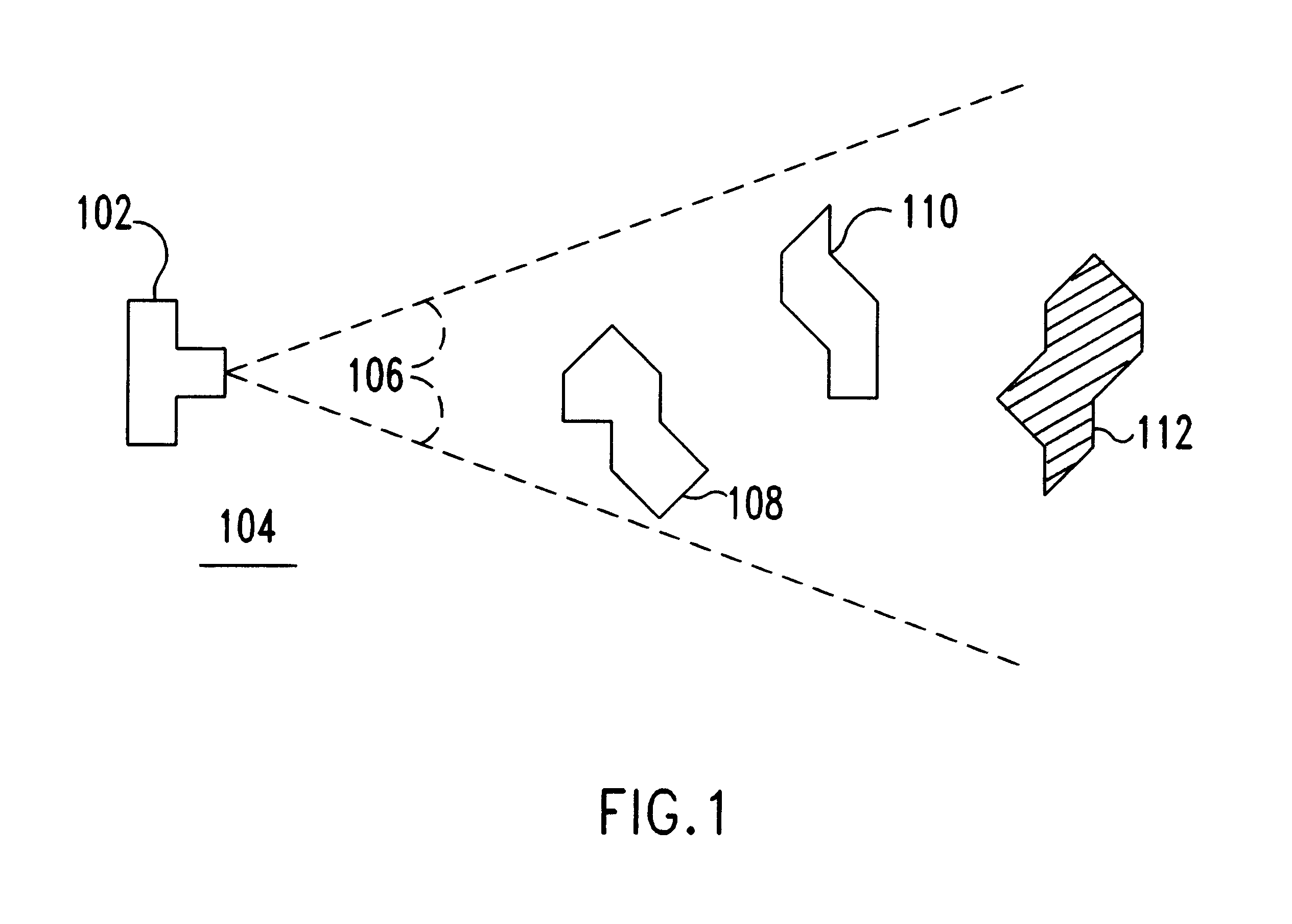
The preferred embodiment of the present invention can best be understood with reference to the arrangement 100 of FIG. 1. In the arrangement 100 a camera 102 at the viewer position 104 views a three dimensional (3D) scene through a view frustum 106, which is also referred to herein as an image volume. Scene objects 108 and 110 in the forefront occlude object 112 (the occludee) from current viewer position 104. Thus, occluded object 112 need not be rendered by computer image processing system rendering the scene as a two dimensional (2D) image. Further, posterior aspects of occluder objects 108, 110, as well as partially occluded features of object 110, need not be rendered. By omitting rendering unnecessary (occluded) scene objects and features, the image processing time is reduced, sometimes dramatically.

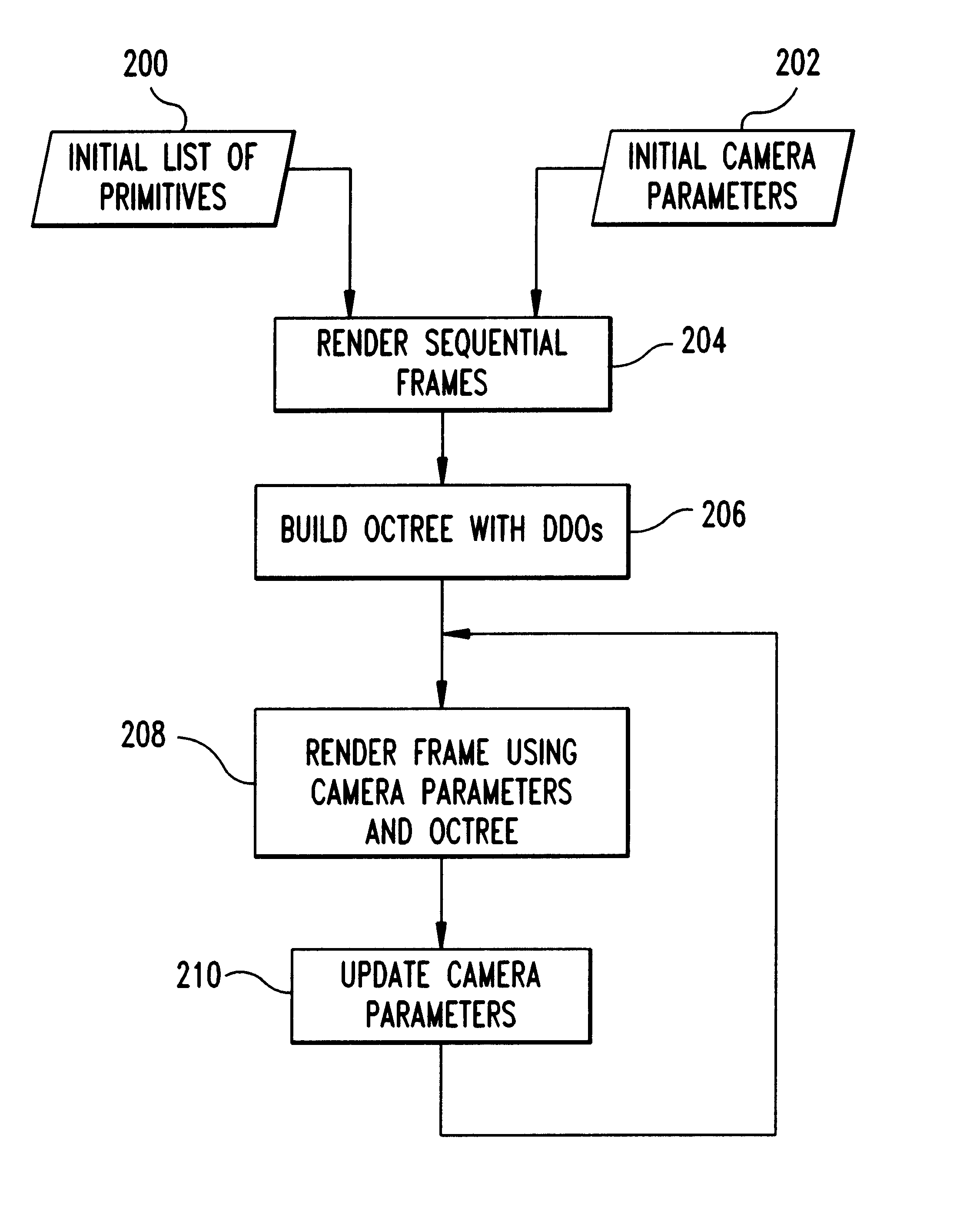
Thus, the present invention is an occlusion culling process or method and system for video imaging scenes such as that in the example of FIG. 1 that includes two major steps or pha...


PUM


Abstract

An occlusion culling method for image processing and system therefor. The culling method first determines which polygons are hidden, or occluded, by other objects. These hidden or occluded polygons will not contribute to the final scene and, therefore, need not be rendered. In the first major step, the input models are preprocessed to build a hierarchical data structure which is as an approximation to the input models. Simple polygonal occluders are determined for substitution in place of the complex image geometry in successive visibility queries. Once the first preprocessing step is complete, the second step may be executed at run-time, while a user is inspecting, or visualizing, the input. In the second step, the occluders, determined in the first step, are used to selectively forego rendering shapes or shape portions that are unseen from the current viewpoint.

Description

1. Field of the InventionThe present invention relates to the field of computer image processing, and more specifically, selectively rendering objects in a scene in image processing systems.2. Background DescriptionState of the art computer aided design (CAD) uses very complex models of objects, wherein each model may include a large number of polygons, that represent physical structures. Interactive visualization of these large polygonal models, places an enormous burden upon the current graphics hardware and makes image rendering very complex and time consuming. This complexity makes it impossible to render at interactive rates with state of the art hardware, especially when interactively rendering large 3D models and is a well known problem in the art. Consequently, numerous methods have been proposed to reduce, or cull, the number of polygons that are rendered for a particular viewpoint and scene model.for example, one such approach, view frustum culling, does not render any pol...

Claims


Application Information

Patent Timeline
IPC IPC(8): G06T15/10G06T15/40
CPCG06T15/40
Inventor BERDARDINI, FAUSTOEL-SANA, JIHADKLOSOWSKI, JAMES T.LUEBKE, DAVIDMENON, JAI
Owner IBM CORP
Why Eureka
Try Eureka