Object lens actuator

Inactive Publication Date: 2007-04-05
HITACHI MEDIA ELECTORONICS CO LTD
View PDF2 Cites 3 Cited by
  • Summary
  • Abstract
  • Description
  • Claims
  • Application Information

AI Technical Summary

Benefits of technology

[0018] Thus, as described above, in accordance with the present invention, an object lens actuator in which the stiffness of the lens holder is improved is provided, by providing a flat plate perpendicular to the focusing direction between the side wall of the lens holding part and the outer sidewall along the tracking direction at approximately the middle of both ends of the lens holder along the focusing direction. Further, by providing the flat plate near the support member fixing points of the lens holder, vibration of the support member fixing parts induced by the weight of solder applied to the support member fixing parts is suppressed. Further, by providing the flat plate at approximately the middle of the lens holder along

Problems solved by technology

However, with such constitution, if the measurement of the lens holder in height (the measurement along the optical axis direction of the object l

Method used


Image

  • Object lens actuator
  • Object lens actuator
  • Object lens actuator

Examples


Example

[First Embodiment]

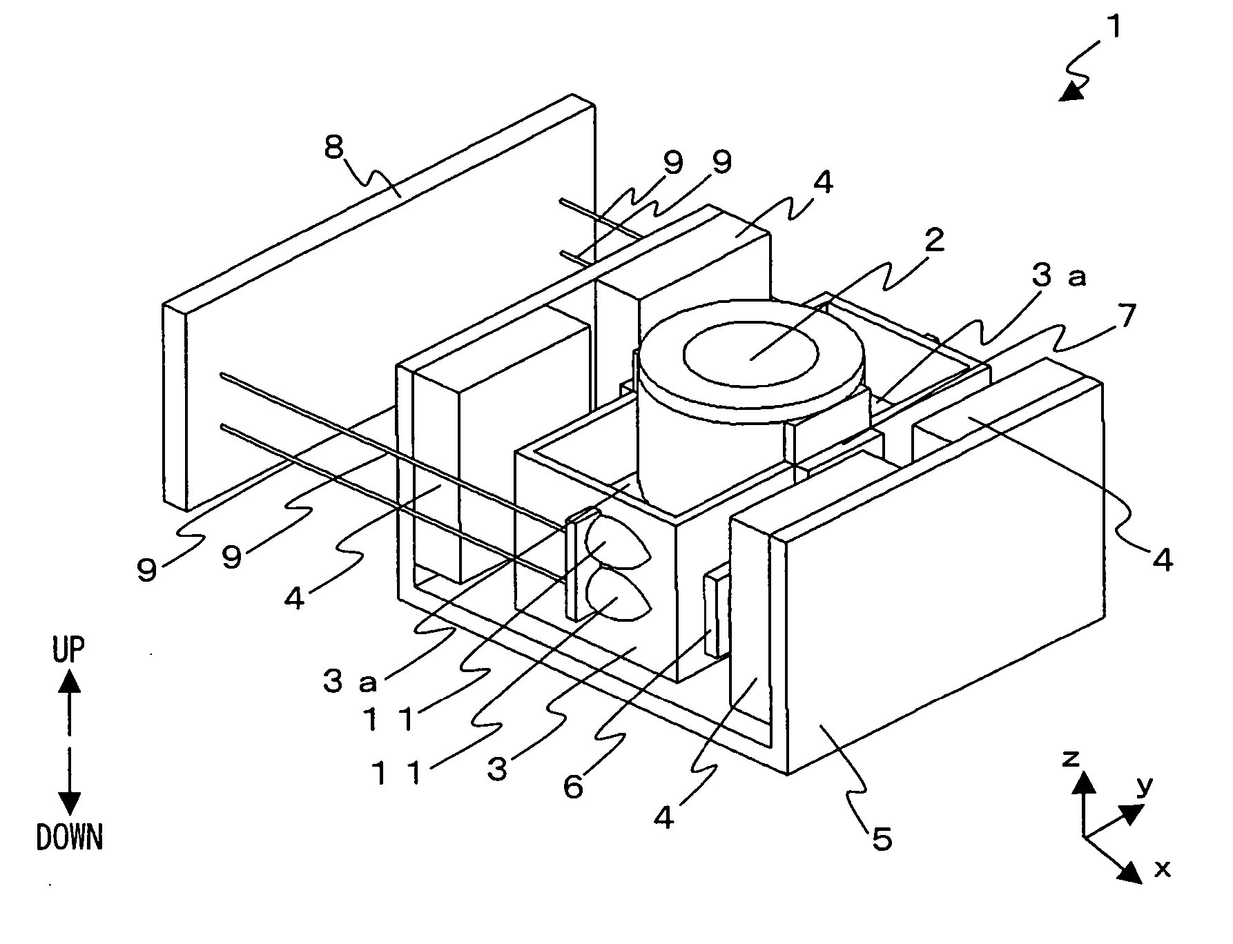
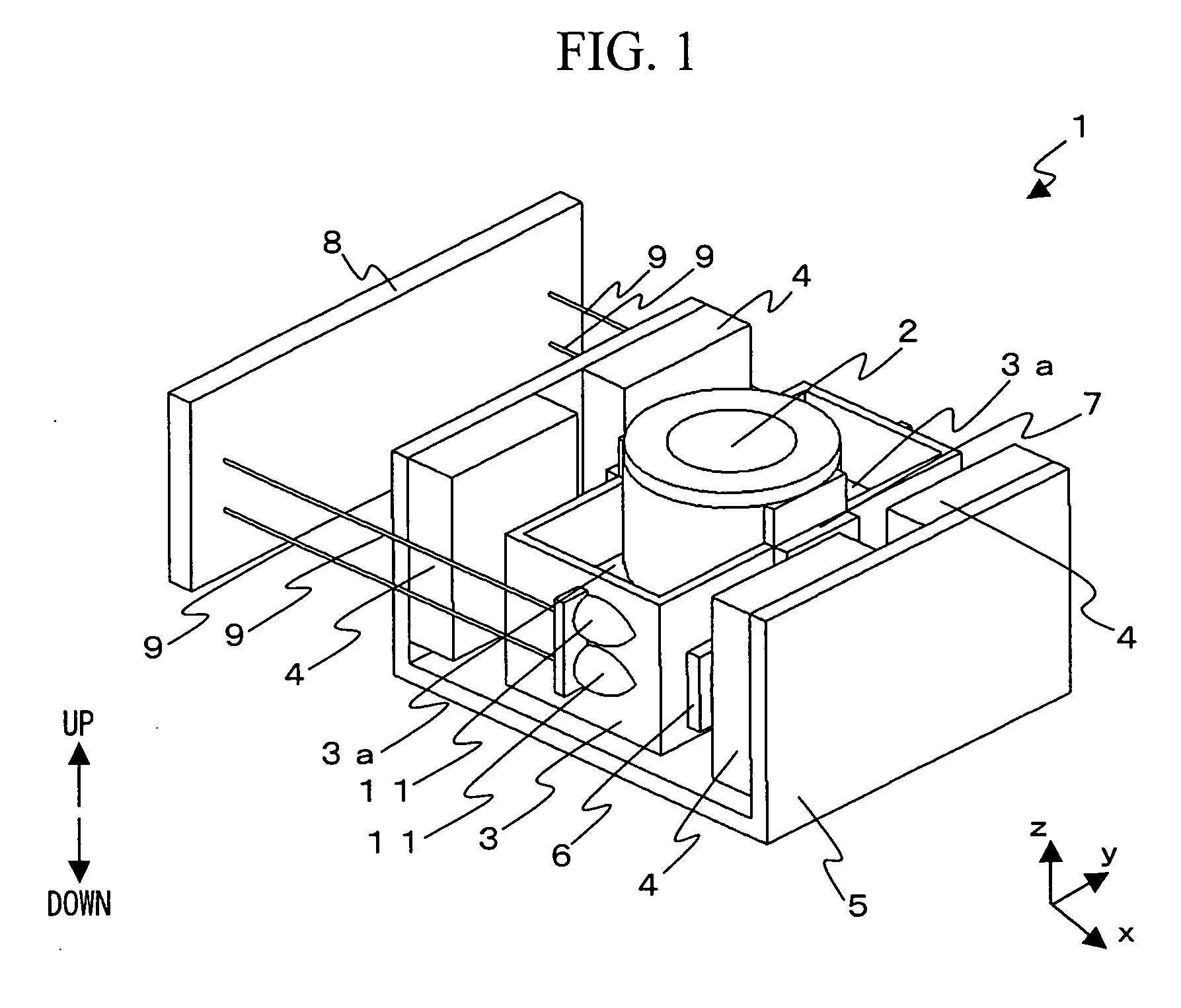
[0028]FIG. 1 schematically shows a perspective view of the overall constitution of an object lens actuator according to a first embodiment. In the following, the x-axis direction shown in each figure refers to a tangential direction of the circumference of an optical disc not shown, the y-axis direction refers to the tracking direction, which is a radial direction of the optical disc, and the z-axis direction refers to the focusing direction, which is the optical axis direction of the object lens. Furthermore, the direction in which the object lens moves closer to the optical disc not shown and the direction in which the object lens moves away from the optical disc not shown are defined as the upward direction and the downward direction, respectively.

[0029] In FIG. 1, an object lens actuator 1 comprises an object lens 2, a lens holder 3 that holds the object lens 2, a fixed part 8 that holds the lens holder 3, support members 9 that elastically support the lens h...

Example

[Second Embodiment]

[0034] Next, an object lens actuator of a second embodiment of the present invention will be described. The overall constitution of the object lens actuator of the present embodiment is similar to that shown in FIG. 1, and the internal shape of the lens holder 3, which is a characterizing portion, will be hereafter described in detail. FIG. 4 shows a cross-sectional view of an object lens 2 and a lens holder 3 of an object lens actuator according to the present embodiment in a plane perpendicular to the x-axis direction. In FIG. 4, the lens holder 3 comprises an aperture stop 3b near the lower end part of the lens holding part 3i, in addition to the same constitution as that of the first embodiment shown in FIG. 2. The aperture stop 3b is formed at a position lower than the center of the core of the tracking coil 7 mounted on the side surface of the lens holder 3.

[0035] In the thus constructed object lens actuator of the present embodiment, the stiffness of the ...

Example

[Third Embodiment]

[0036] Next, an object lens actuator of a third embodiment of the present invention will be described. The overall constitution of the object lens actuator of the present embodiment is similar to that shown in FIG. 1, and the internal shape of the lens holder 3, which is a characterizing portion, will be hereafter described in detail. FIG. 5 shows a cross-sectional view of an object lens 2 and lens holder 3 of an object lens actuator according to a present embodiment in a plane perpendicular to the x-axis direction. In FIG. 5, in the cross section shown, the lens holder 3 has a pair of holes 3c that run through both sides of the flat plate 3a, in addition to the same constitution as that of the second embodiment shown in FIG. 4. The location and the shape of this pair of holes 3c are substantially symmetrical with respect to the optical axis of the object lens 2. Alternatively, three or more holes substantially symmetrical with respect to the optical axis of the o...


PUM


Abstract

In an object lens actuator, stiffness of a lens holder is improved and the higher order resonance frequency is sufficiently increased. The stiffness of the lens holder is improved by providing a flat plate perpendicular to the focusing direction between the side wall of a lens holding part and the outer sidewall along the tracking direction at approximately the middle of both ends of the lens holder along the focusing direction.

Description

BACKGROUND OF THE INVENTION [0001] 1. Field of the Invention [0002] The present invention relates to an object lens actuator used in an optical disc drive that writes / reads information in / from an optical disc. Particularly, the invention relates to an object lens actuator in which the stiffness of an object lens holder is improved. [0003] 2. Background Art [0004] In an optical disc write / read drive that writes / reads information in / from a disc-type information recording medium, attempts have been made to improve the data transfer speed by spinning the disc at high speed. In order to accurately write / read information in / from the rapidly spinning optical disc, such optical disc write / read drive mounts an object lens actuator that drives an object lens in the focusing direction and the tracking direction so that the lens follows a recording surface of the optical disc. [0005] A general object lens actuator comprises a magnetic circuit composed of a yoke and a permanent magnet, a movable...

Claims


Application Information

Patent Timeline
IPC IPC(8): G11B7/00G02B7/04
CPCG11B7/0935G11B7/22
Inventor OCHI, MANABUKIMURA, KATSUHIKOSAITO, HIDENAOHATO, JUN
Owner HITACHI MEDIA ELECTORONICS CO LTD
Why Eureka
Try Eureka