
Converting device for automatic toilet flushing and air deodorizing

a technology of automatic toilet flushing and conversion device, which is applied in the direction of flushing device, water installation, construction, etc., can solve the problems of no mechanism for water quantity control, no deodorizing mechanism, complex control circuit, etc., and achieves the effect of easy integration and relatively low cos

Inactive Publication Date: 2007-04-12
SHOIKHET ISAAK +1
View PDF6 Cites 20 Cited by
  • Summary
  • Abstract
  • Description
  • Claims
  • Application Information

AI Technical Summary

Benefits of technology

[0034] The additional object of the present invention is to create an improved toilet flushing and air deodorizing system, which can be installed at a relatively low cost without using any special tools and skills of the user.
[0035] The further object of the present invention is to create an improved toilet flushing and air deodorizing system assembled in its own housing, which can be easily joined to the flushing means of the conventional toilet.
[0038] It makes possible to use the various sprays (and another bulbs with the deodorant as well) produced in a wide assortment, which can be actuated by pressing the discharge valve (piston). The invention consists of the simple in manufacturing mechanical details and the cheap mechanical and electric elements and units as well.

Problems solved by technology

Many people experience the temporary or constant difficulties, which can prevent the free pressing of the toilet handle, for example hospitalized persons.
Furthermore, they have no mechanism for the water quantity control and have no deodorizing mechanism.
More by token, two last systems have very complex and expensive control circuits.
Thereby the existing automatic flush systems cannot be used without changes of the flushing mechanism or without its full replacement.
Furthermore the full replacement of the flushing system or its re-equipment demands big charges.
Moreover, all existing deodorizing devices are not adapted for the coordinated work with the automatic flush system and cannot be used without any change of the mechanism inside the domestic device.

Method used


Image

  • Converting device for automatic toilet flushing and air deodorizing
  • Converting device for automatic toilet flushing and air deodorizing
  • Converting device for automatic toilet flushing and air deodorizing

Examples


Embodiment Construction

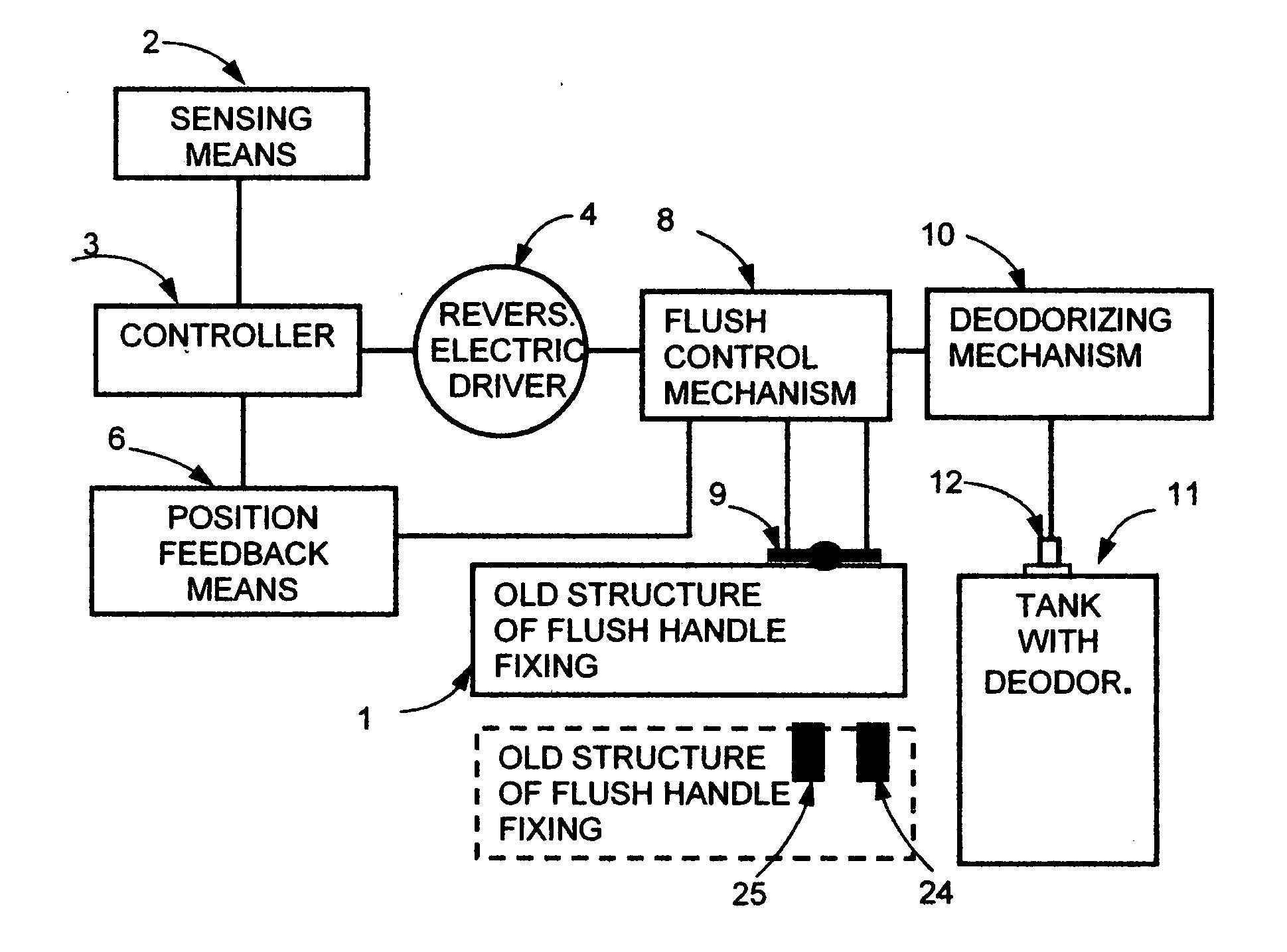
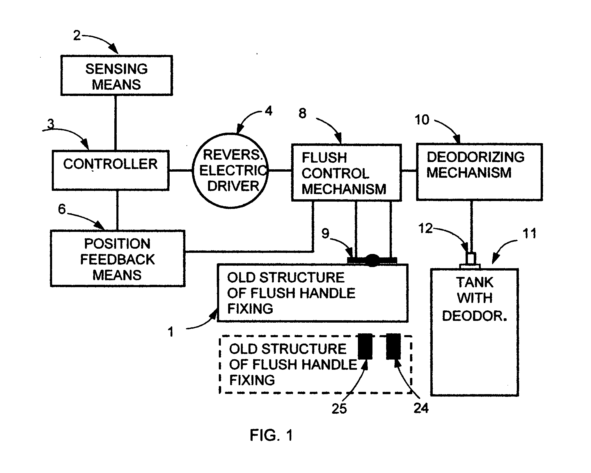
[0061] The block diagram of the invention, including its basic units, is shown on FIG. 1. All electric units—the sensing means 2, the controller 3, the reversible electric driver 4—are supplied with one electric power source or several electric power sources (not shown on FIG. 1)

[0062] The sensing means 2 creates a presence signal (or a signal of the toilet using), if the user is present in a zone of the toilet use. A character of the presence signal (for example, frequency, duration, on-off ratio etc.) depends on the duration of the toilet using. The presence signal is transferred from the sensing means 2 to the controller 3 as a beam of radiation. In another embodiment the sensing means 2 is a converter, which is located in a zone of the toilet use (on the floor directly in a front of the toilet bowl, or under the bowl seat, or under the bowl) and is sensitive to the user's weight. In the simplest embodiment, the sensing means 2 is at least one micro switch with a normally opened...


PUM


Abstract

The invention converts a conventional domestic toilet into a system with automatic control of flushing water quantity and air deodorizing without any change of an internal flushing mechanism. A sensing means generates a presence signal, if a user is present in a toilet usage zone. A reversible electric driver actuates the existing toilet flush handle with the flush control mechanism and actuates a deodorant discharge valve with the deodorizing mechanism. A position feedback means defines in what position is located the flush control mechanism. A controller receives and processes the position feedback signals and the presence signals as well and makes the reversible electric driver to move, to stop or to change the movement direction. The invention is applicable for all toilets with pressure-type water flush system and with a water tank system comprising one or two manual flush handles.

Description

THE FIELD AND THE BACKGROUND OF THE INVENTION [0001] This invention refers to improvements of toilet flush systems and, more particularly, to retrofit devices for conversion an usual toilet flush system for the private dwelling to the automatic flush system with control of the flush water quantity and with the air deodorizing in necessary cases. [0002] The water economy is very important in many regions of the planet. It concerns first of all to all big cities and territories with the high population density, including the USA. One way of the water spending is connected with the water closet usage, for as much as for each toilet flushing in the domestic toilets with manual control is being spent from 3 up to 5 gallons of the fresh water. It is desirable to provide an automatic control of the flush water quantity with reduced water quantity for a liquid waste. [0003] It is desirable to create an automatic flush system for use in private dwellings for other reasons as well. Many peopl...

Claims


Application Information

Patent Timeline
IPC IPC(8): E03D5/10
CPCE03D5/10E03D9/007
Inventor SHOIKHET, ISAAKHAIN, VITALIJ JAKOVLEVICH
Owner SHOIKHET ISAAK
Learn More