Upright vacuum cleaner

Inactive Publication Date: 2007-04-12
LG ELECTRONICS INC
View PDF11 Cites 150 Cited by
  • Summary
  • Abstract
  • Description
  • Claims
  • Application Information

AI Technical Summary

Benefits of technology

[0012] An object of the present invention is to provide a vacuum cleaner which has a simple coupling structure, and is convenient in use.
[0013] Another object of the present invention is to provide a vacuum c

Problems solved by technology

Such prior cyclonic airflow upright vacuum cleaner has a problem in that the airflow passes through a cyclonic chamber without being filtered.
Also, in the conventional

Method used


Image

  • Upright vacuum cleaner
  • Upright vacuum cleaner
  • Upright vacuum cleaner

Examples


Embodiment Construction

[0049] Reference will now be made in detail to the preferred embodiments of the present invention, examples of which are illustrated in the accompanying drawings.

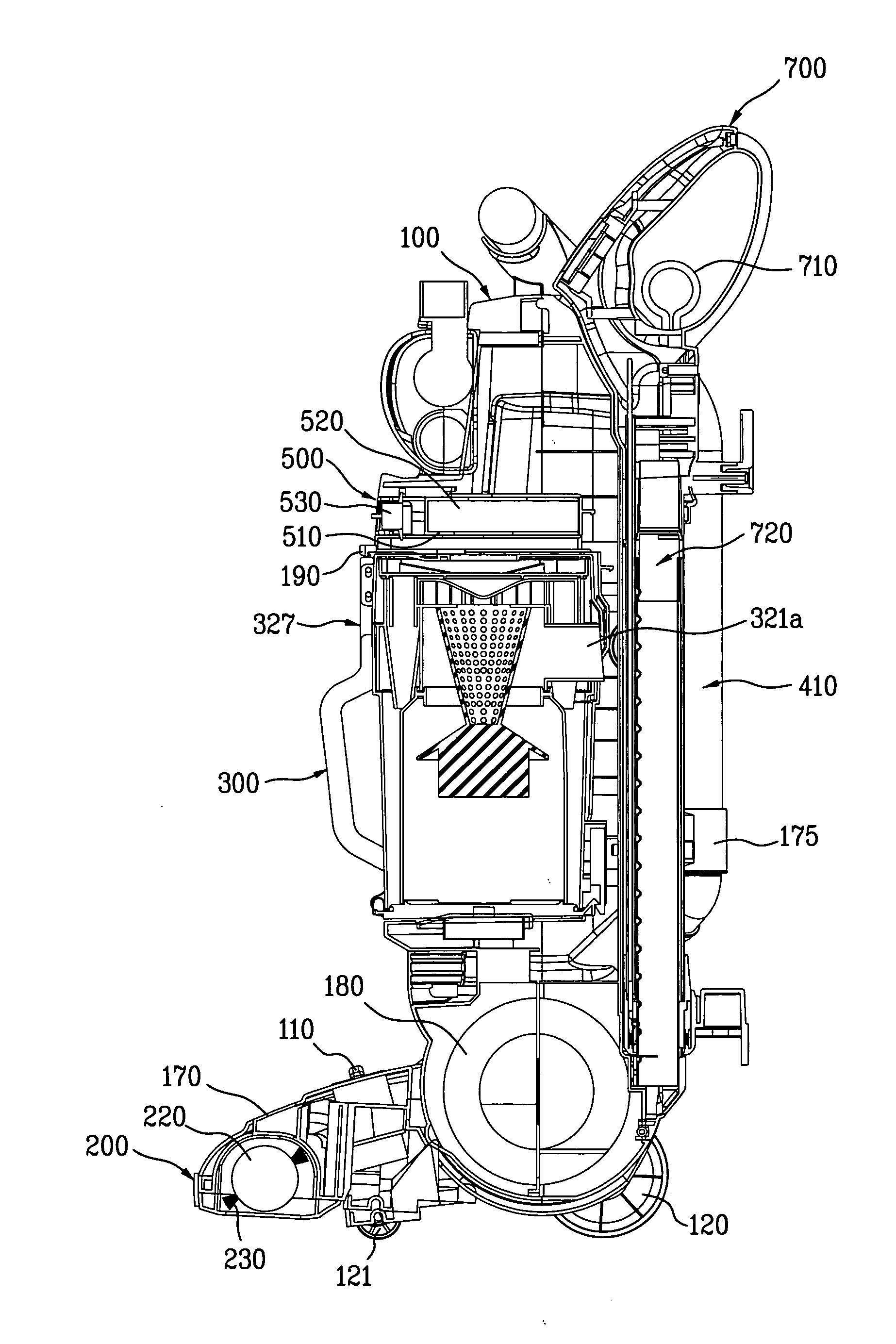
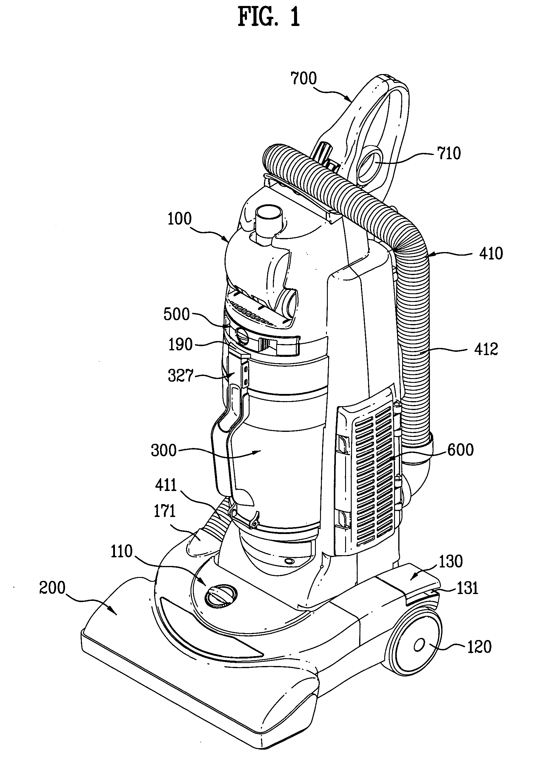
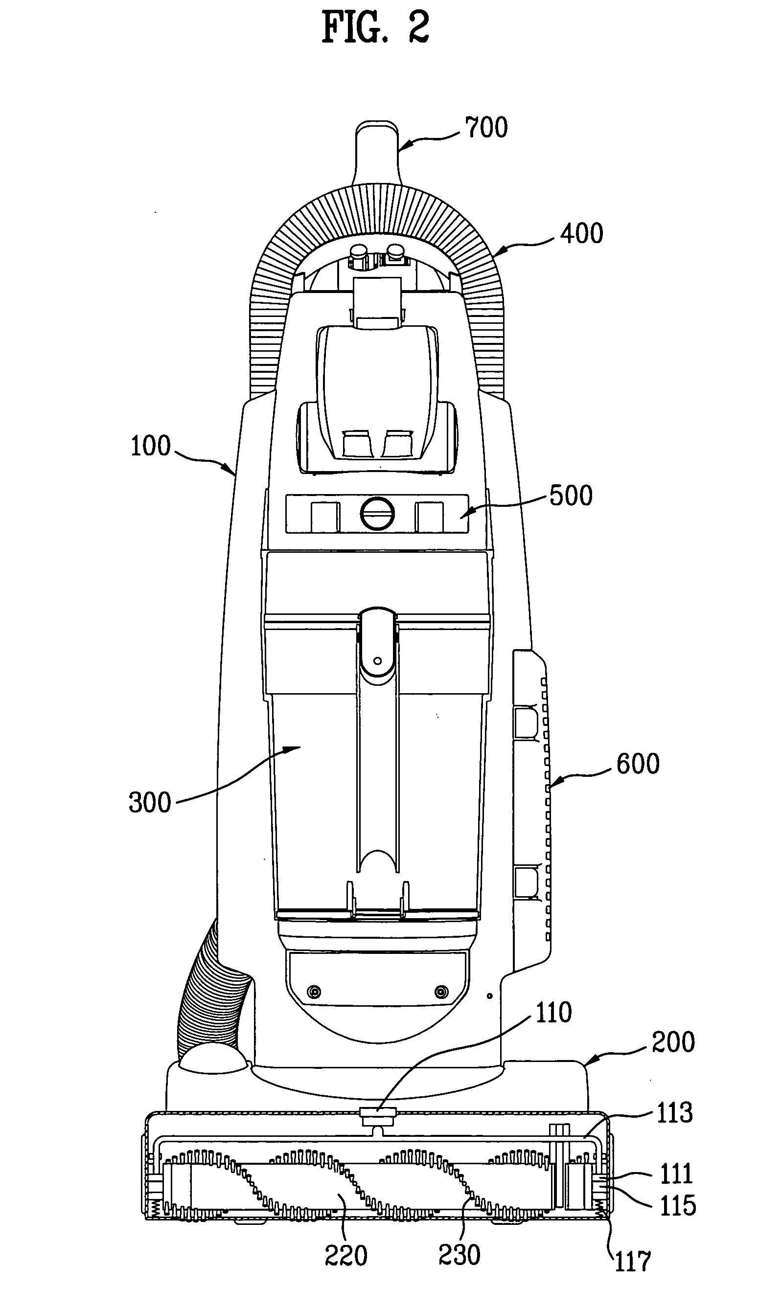
[0050]FIGS. 1-6 illustrate an upright vacuum cleaner including a cleaner body 100, a nozzle section 200 connected to the cleaner body 100, and conduits for guiding the suction airflow from the nozzle section 200 to the atmosphere through the cleaner body 100.

[0051] The cleaner body 100 and the nozzle section 200 are pivotally or hingedly connected through the use of suitable hinge assembly so that the cleaner body 100 pivots between a generally vertical storage position (as shown) and an inclined operative position.

[0052] The nozzle section 200 includes a nozzle case 210, a suction opening 211 which formed at the underside of the nozzle case 210, and a rotating brush assembly which provided in the nozzle case 210. Front wheels 121 and rear wheels 121 are rotatably mounted to underside of the nozzle case 210, respectively...


PUM


Abstract

A vacuum cleaner is disclosed. The vacuum cleaner comprises a cleaner body, a multi cyclonic a primary cyclone and at least one secondary cyclone, a suction source having a suction source inlet and a suction source outlet, a main filter assembly including a main filter element comprising a selectively permeable material, a discharge member having an opened upper end coupled to the peripheral edge of the primary airflow outlet and a closed lower end, and a guide rib provided at the primary cyclone for guiding the airflow in a direction tangential to the inner peripheral wall surface of the primary cyclone. Accordingly, it is possible to separate easily and conveniently dust and dirt from the airflow and deposit the dust and dirt into the dust collecting container.

Description

BACKGROUND OF THE INVENTION [0001] 1. Field of the Invention [0002] The present invention relates to vacuum cleaners. More particularly, the present invention relates to upright vacuum cleaners used for suctioning dirt and dust from carpets and floors. [0003] 2. Discussion of the Related Art [0004] Upright vacuum cleaners are known to include a cleaner body having a handle, by which an operator of the vacuum cleaner may grasp and maneuver the cleaner, and a nozzle section which travels across a floor, carpet, or other surfaces being cleaned. [0005] The cleaner body often formed as a rigid plastic housing which encloses a dirt and dust collecting filter bag. The nozzle section is hingedly connected to the cleaner body such that the cleaner body is pivotable between a generally vertical upright storage position and an inclined operative position. The underside of the nozzle section includes a suction opening formed therein which is in fluid communication with the filter bag. [0006] A ...

Claims


Application Information

Patent Timeline
IPC IPC(8): A47L9/16
CPCA47L5/34A47L9/122A47L9/1625A47L9/1641A47L9/165A47L9/1658A47L9/1666A47L9/1683A47L9/325
Inventor MIN, YOUNG GUNKIM, JAE KYUM
Owner LG ELECTRONICS INC
Why Eureka
Try Eureka