
Systems and Methods for a User Interface for Electronic Weaponry

a technology of electronic weapons and user interfaces, applied in the field of weapons, can solve the problems of limited useful range, limited application of conventional electronic weapons, and interference of electric current flowing through parts of the target's tissue, and achieve the effect of preventing locomotion

Active Publication Date: 2007-04-12
AXON ENTERPRISE INC
View PDF26 Cites 25 Cited by
  • Summary
  • Abstract
  • Description
  • Claims
  • Application Information

AI Technical Summary

Benefits of technology

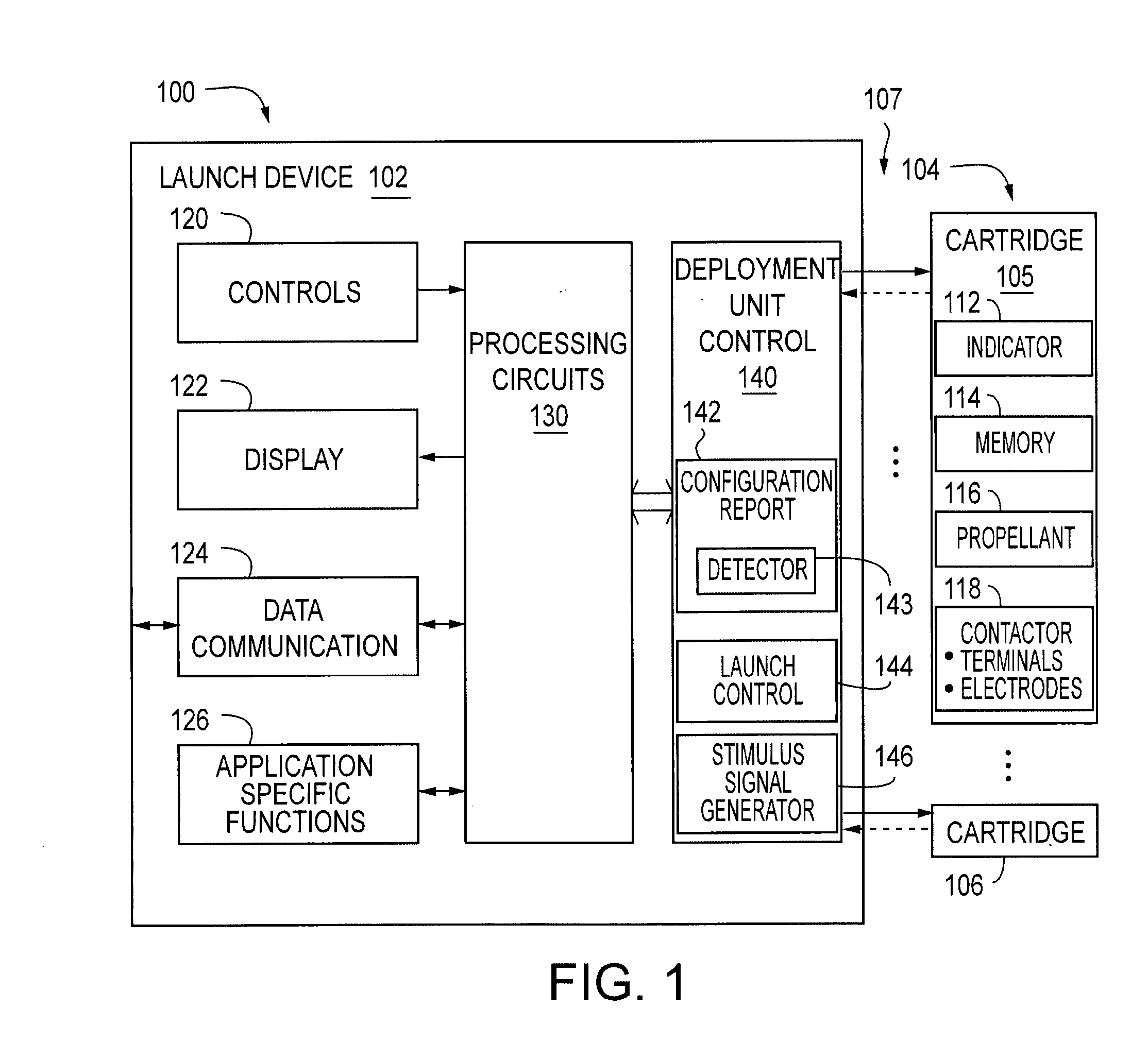
The present invention provides an apparatus for producing contractions in skeletal muscles of a target to impede locomotion by the target. The apparatus includes a stimulus signal generator that determines the current, and a detector that detects indicia of the deployment unit. The apparatus can be used with a provided deployment unit that deploys an electrode away from the apparatus. The method includes storing in a memory the time of the deployment performed by the apparatus and transmitting an identification of the apparatus through a wireless link. The technical effects of the invention include improved accuracy and efficiency in producing contractions in skeletal muscles for the purpose of impeding locomotion by the target.

Problems solved by technology

This type of weaponry when used against a human or animal target causes an electric current to flow through part of the target's tissue to interfere with the target's use of its skeletal muscles.
Conventional electronic weaponry has limited application, limited useful range, and limited accuracy.

Method used


Image

  • Systems and Methods for a User Interface for Electronic Weaponry
  • Systems and Methods for a User Interface for Electronic Weaponry
  • Systems and Methods for a User Interface for Electronic Weaponry

Examples


Embodiment Construction

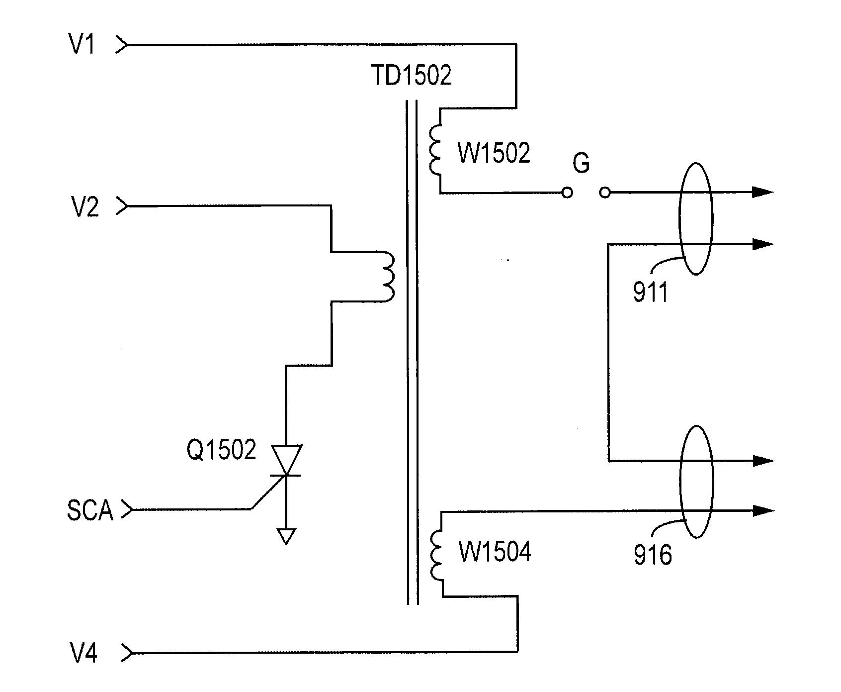
[0034] Greater utility and improved accuracy of electronic weapon systems can be obtained by eliminating several problems exhibited by conventional electronic weapon systems. A conventional electronic weapon may perform a contact (or proximate) stun function (also called a local stun function) of subduing an animal or person (herein called a target) by abutting (or bringing proximate) at least two terminals of the weapon to the skin or clothing of the target. Another conventional electronic weapon may perform a remote stun function of subduing a target by launching one or more wire tethered electrodes from the weapon to the target so that the electrodes are proximate to or impale the skin or clothing of the target. In either the local stun function or the remote stun function, an electric circuit is formed for passing a pulsing current through a portion of the tissue of the target to interfere with skeletal muscle control by the target. When a terminal or an electrode is proximate t...


PUM


Abstract

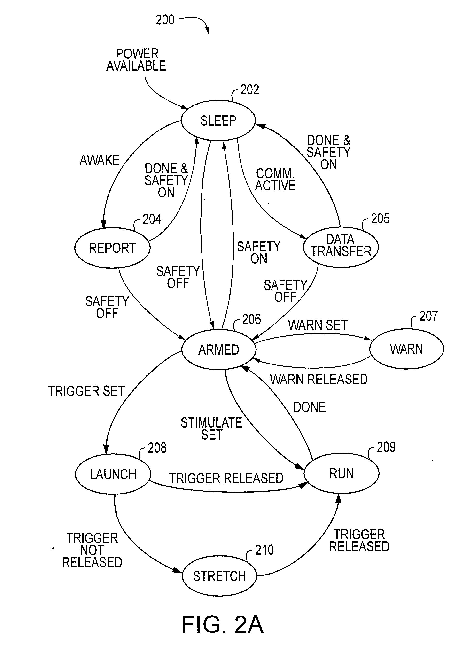
Another apparatous, according to various aspects of the present invention, produces contraction in skeltal muscles of a target to impede locomotion by the target. The apparatus is used with a provided deployment unit that deploys an electrode away from the apparatus. The electrode conducts a current through the target. The apparatus includes a terminal; producing sub-system for producing an electric arc to warn the target without conducting a current through the target; conducting sub-system for conducting the current in series through the terminal and through the target; initiating sub-system for inititaing deployment of the electrode; and an operator interface. The operator interface further facilitates, prior to deployment of the electrode, repeated operation of any one or both of the producing sub-system and the conducting sub-system. The operator interface further facilitates,after deployment of the electrode, repeated operation of any one or both of the conducting sub-system and the initiating sub-system, each operation of the initiating sub-system being with a respective further electrode of the deployment unit.

Description

CROSS-REFERENCE TO RELATED APPLICATIONS [0001] This application claims the benefit of U.S. Provisional Patent Application No. 60 / 716,809 filed Sep. 13, 2005 by Nerheim, et al., incorporated herein by reference.FIELD OF THE INVENTION [0002] Embodiments of the present invention relate to weaponry including electronic control devices. BACKGROUND OF THE INVENTION [0003] Conventional electronic weaponry includes, for example, contact stun devices, batons, shields, stun guns, hand guns, rifles, mortars, grenades, projectiles, mines, and area protection devices among other apparatus generally suitable for ensuring compliance with security and law enforcement. This type of weaponry when used against a human or animal target causes an electric current to flow through part of the target's tissue to interfere with the target's use of its skeletal muscles. All or part of an electronic circuit may be propelled toward the target. In an important application of electronic weaponry, terrorists may ...

Claims


Application Information

Patent Timeline
Patent Type & Authority Applications(United States)
IPC IPC(8): H01T23/00
CPCF41H13/0018F41H13/0025F41H13/0087H05C1/06F41A17/063F41A17/066F41B6/00
Inventor BRUNDULA, STEVEN N.D.CEROVIC, MILANNERHEIM, MAGNE H.
Owner AXON ENTERPRISE INC
Learn More