X-ray computed tomographic apparatus

Inactive Publication Date: 2007-04-12
TOSHIBA MEDICAL SYST CORP
View PDF5 Cites 44 Cited by
  • Summary
  • Abstract
  • Description
  • Claims
  • Application Information

AI Technical Summary

Benefits of technology

[0010] Accordingly, it is an object of the present invention to provide an X-ray computed tomographic apparatus having a

Problems solved by technology

However, since a portion in which some of the image is lost is changed in a top or bottom, left or right direction corresponding to

Method used


Image

  • X-ray computed tomographic apparatus
  • X-ray computed tomographic apparatus
  • X-ray computed tomographic apparatus

Examples


Example

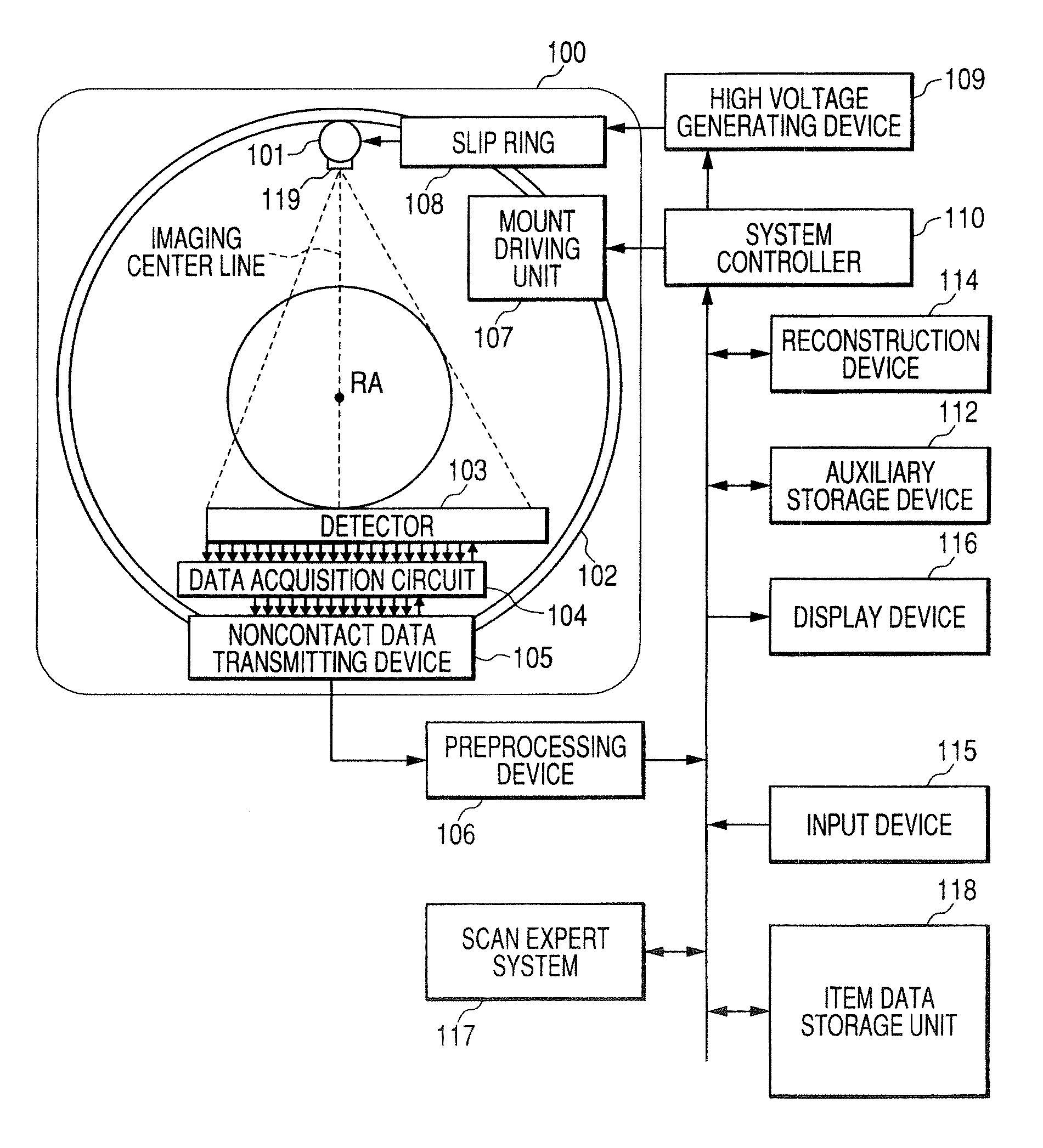
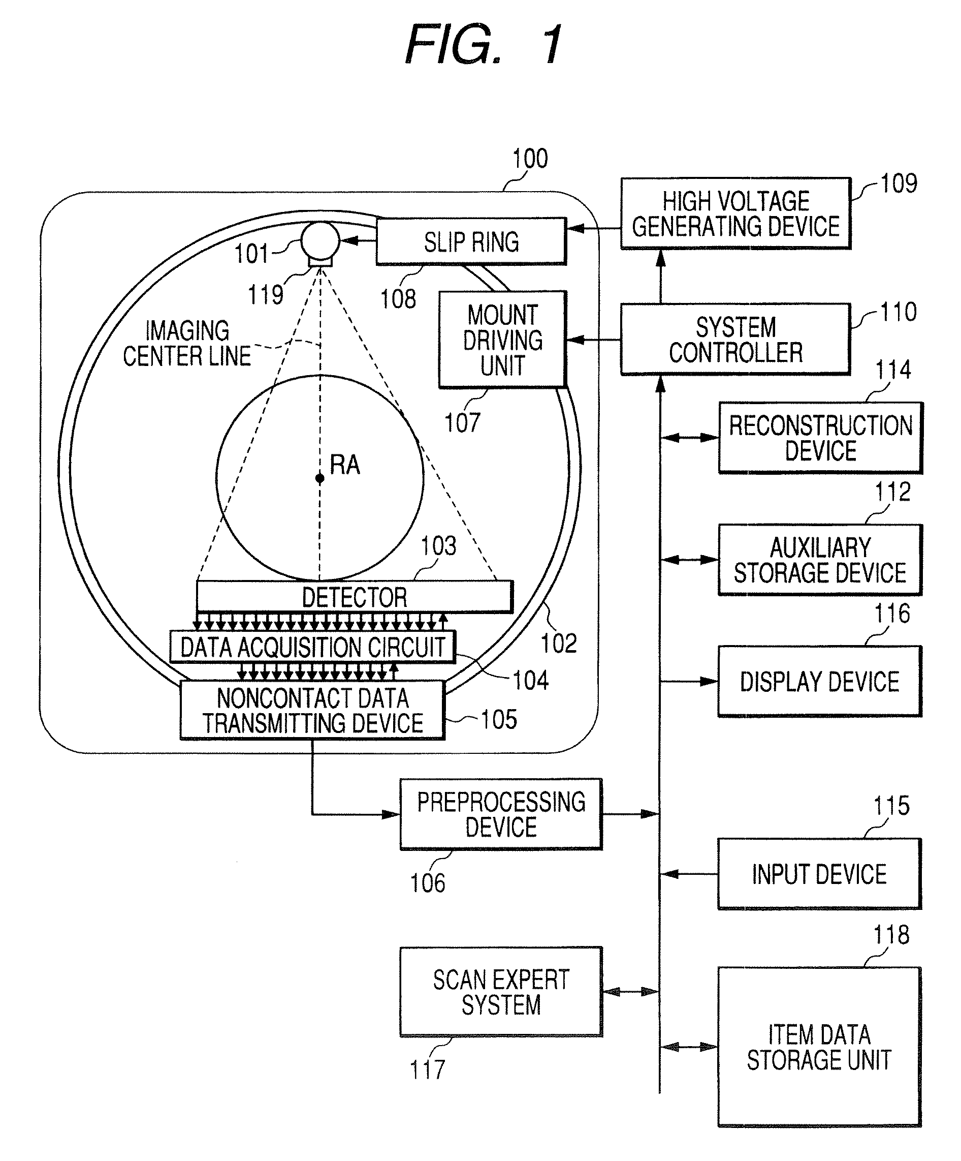
[0036] Hereinafter, embodiments of this invention will be described with reference to accompanying drawings. In order to reconstruct one slice of tomographic image data in an X-ray computed tomographic apparatus, 360° projection of the object is required so as to obtain data. Further, even when using a half scanning method, projection data corresponding 180°+ view angle is required. This invention is applicable for any type of reconstruction methods. Hereinafter, the half scanning method will be exemplified. A mechanism that converts incident X-ray into electric charges mainly includes an indirect conversion method and a direct conversion method. The indirect conversion method converts the X-ray into light using a fluorescent substance such as a scintillator and then converts the light into electric charges using a photoelectric conversion element such as a photodiode. Further, the direct conversion method uses a photoconductive effect, that is, generates an electron-hole pair in a ...


PUM


Abstract

An X-ray computed tomographic apparatus includes an X-ray tube that generates X-ray, an X-ray detector that detects an X-ray passing through an object, a supporting member that rotatably supports the X-ray tube and the X-ray detector around a rotational axis, a reconstructing unit that reconstructs an image on the basis of an output of the X-ray detector, an information creating unit that creates information concerning an arrangement of an asymmetrical field of view of the object when the field of view of the scanogram by the X-ray tube and the X-ray detector is asymmetric with respect to an imaging center line in a direction perpendicular to the rotational axis, and a display unit that displays information concerning the created arrangement.

Description

CROSS-REFERENCE TO RELATED APPLICATIONS [0001] This application is based upon and claims the benefit of priority from prior Japanese Patent Application No. 2005-244435, filed Aug. 25, 2005, the entire contents of which are incorporated herein by reference. BACKGROUND OF THE INVENTION [0002] 1. Field of the Invention [0003] The present invention relates to an X-ray computed tomographic apparatus having an asymmetrical X-ray detector. [0004] 2. Description of the Related Art [0005] The asymmetrical X-ray detector includes an X-ray detector in which a detection region of X-ray that passes through an object is asymmetric with respect to an imaging center line in a channel direction. In detail, in the asymmetrical X-ray detector, the imaging center line is disposed between X-ray detecting channels, and the number of X-ray detecting channels that is positioned at one side of the imaging center line is larger than the number of X-ray detecting channels that is positioned at the other side ...

Claims


Application Information

Patent Timeline
IPC IPC(8): H05G1/60A61B6/00G01N23/00G21K1/12
CPCA61B6/032A61B6/463A61B6/465G01N2223/419A61B6/587G01N23/046A61B6/467
Inventor NABATAME, TAKEO
Owner TOSHIBA MEDICAL SYST CORP
Why Eureka
Try Eureka