Milling cutter head and a milling cutter tool

a milling cutter and cutter head technology, applied in the direction of milling cutters, attachable milling devices, manufacturing tools, etc., can solve the problems of lack of teaching of how the milling cutter head in practice could be detachable, lack of means to transfer torque from the basic body to the milling cutter head, and low production efficiency

Inactive Publication Date: 2007-04-12
SANDVIK INTELLECTUAL PROPERTY AB
View PDF19 Cites 35 Cited by
  • Summary
  • Abstract
  • Description
  • Claims
  • Application Information

AI Technical Summary

Benefits of technology

[0007] Another object of the invention is to provide a milling cutter head having a geometry that allows the formation of a large number of cutting edges located close to each other as well as the appurtenant chip flutes.

Problems solved by technology

However, long cutting edges are rarely utilized even along the major part of the length thereof.
These utmost scanty teachings are, however, only of theoretical character, so far that the document lacks any teaching of how the milling cutter head in practice could be detachably connected to the basic body in a stable and reliable way.
Among other things, any means to transfer torque from the basic body to the milling cutter head is lacking in the construction.

Method used


Image

  • Milling cutter head and a milling cutter tool
  • Milling cutter head and a milling cutter tool
  • Milling cutter head and a milling cutter tool

Examples


Embodiment Construction

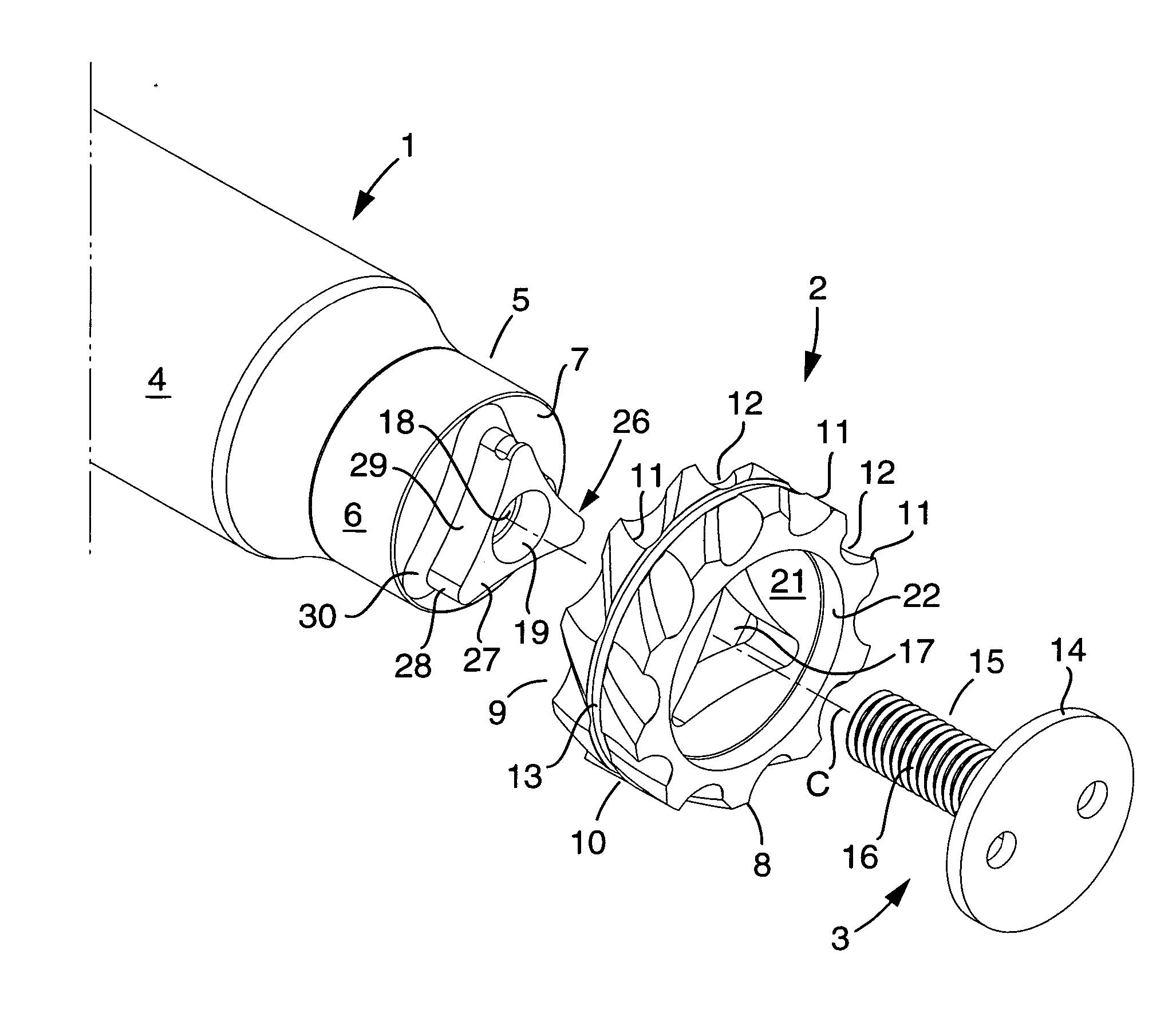
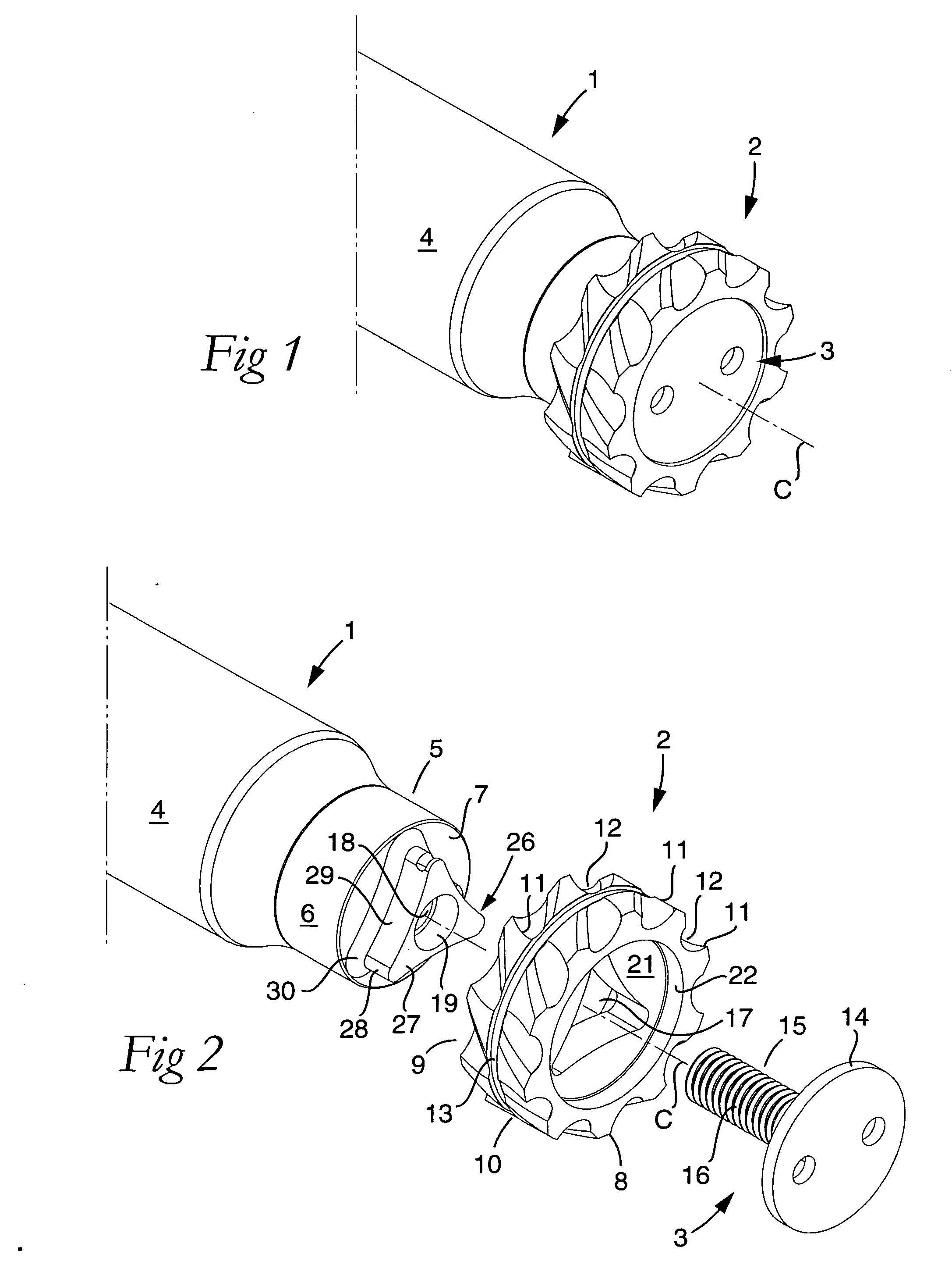
[0022] In FIGS. 1 and 2, a milling cutter tool made in accordance with the invention is shown, and which is composed of a rotatable basic body 1 and a replaceable milling cutter head 2. For the fixation of the milling cutter head on the basic body, a tightening device 3 is used, which in the embodiment shown is in the form of a screw mounted from the front. In the example, not only the milling cutter head 2, but also the basic body 1, has a rotationally symmetrical basic shape defined by a central axis C around which the tool is rotatable. Advantageously—though not necessarily—the basic body 1 has an elongate shape, and is, in this case, delimited along the major part of the length thereof by a cylindrical envelope surface 4. At the front, free end thereof, the basic body transforms into a thinner, male-like member 5, which is delimited by a rotationally symmetrical envelope surface 6, as well as a planar end surface 7. Most suitably, the envelope surface 6 is cylindrical.

[0023] Th...


PUM

PropertyMeasurementUnit
diameteraaaaaaaaaa
shapeaaaaaaaaaa
thickaaaaaaaaaa

Abstract

A milling cutter head in the form of a body, which has an external envelope surface having a rotationally symmetrical basic shape in respect of a central axis, and includes a plurality of peripherally spaced-apart cutting edges and chip flutes. The cutter head includes two axially spaced-apart ends in which hollow spaces open, which are arranged to receive male elements included in a basic body, and are spaced-apart by a partition wall in which a through hole is formed. The through hole mouths in bottom surfaces in the hollow spaces. The cross-section area of each individual hollow space, in a plane perpendicular to the center axis, amounts to at least 25% of the total cross-section area of the body, as defined by the greatest diameter of the envelope surface.

Description

[0001] This application claims priority under 35 U.S.C. § 119 to Swedish Patent Application No. 0502206-6, filed on Oct. 5, 2005, the disclosure of which is incorporated by reference herein in its entirety. FIELD OF THE INVENTION [0002] The present invention relates generally to a replaceable milling cutter head in the form of a body, which has, on one hand, an external envelope surface, which has a rotationally symmetrical basic shape in respect of a central axis, and includes a plurality of peripherally spaced-apart cutting edges and chip flutes, and, on the other hand, two axially spaced-apart front and rear ends in which hollow spaces open, which are arranged to receive male elements included in a basic body, and spaced-apart by a partition wall in which a through hole is formed, which mouths in bottom surfaces in the hollow spaces. The present invention also relates generally to a milling cutter tool having such a milling cutter head. BACKGROUND OF THE INVENTION [0003] Replacea...

Claims


Application Information

Patent Timeline
Patent Type & Authority Applications(United States)
IPC IPC(8): B23C5/00
CPCB23C5/10B23C2210/02Y10T409/30952B23C2210/243B23C2210/03B23C5/06B23C5/08B23C5/22
Inventor BLOMSTEDT, PERLEHTO, RALF
Owner SANDVIK INTELLECTUAL PROPERTY AB
Why Eureka
Try Eureka