Lancet device, removal system for lancet device, and method

a technology of lancet and removal system, which is applied in the field of lancet device and removal system for lancet device, can solve the problems that many users simply cannot perform the procedure, the procedure is often problematic for the user, and the control of the depth of penetration cannot be reliably accomplished withou

Inactive Publication Date: 2007-04-12
STAT MEDICAL DEVICES
View PDF9 Cites 161 Cited by
  • Summary
  • Abstract
  • Description
  • Claims
  • Application Information

AI Technical Summary

Benefits of technology

[0073] The invention also provides a method of puncturing a surface of skin using the lancet device described above, wherein the method comprises adjusting a depth of penetration by rotating the adjustment mechanism to a desired set depth position, disposing the skin engaging end against a user's skin, and triggering the trigger to cause the lancet needle to penetrate the user's skin, wherein the adjusting does not change a position of the stop surface relative to the body and changes an overall length of the lancet device.

Problems solved by technology

However, this procedure is often problematic for the user since the needle may be difficult to handle.
Moreover, controlling the depth of penetration cannot be reliably accomplished without the use of a mechanical device.
Additionally, many users simply cannot perform the procedure owing to either a fear of needles or because they lack a steady hand.
Most lancet devices lack convenient and flexible adjustability.
This, of course, creates the problem of storing the replaceable tips, which if not properly done, may result in their misplacement, damage contamination, or the like.
The SLAMA device is characterized as a □single bottom□ device which employs a threaded design which can be expensive to manufacture.
Further, such a threaded resign is prone to inadvertent setting changes since there is nothing but frictional engagement between the mating threads to maintain the adjustment setting.

Method used


Image

  • Lancet device, removal system for lancet device, and method
  • Lancet device, removal system for lancet device, and method
  • Lancet device, removal system for lancet device, and method

Examples


Embodiment Construction

[0168] The particulars shown herein are by way of example and for purposes of illustrative discussion of the embodiments of the present invention only and are presented in the cause of providing what is believed to be the most useful and readily understood description of the principles and conceptual aspects of the present invention. In this regard, no attempt is made to show structural details of the present invention in more detail than is necessary for the fundamental understanding of the present invention, the description taken with the drawings making apparent to those skilled in the art how the several forms of the present invention may be embodied in practice.

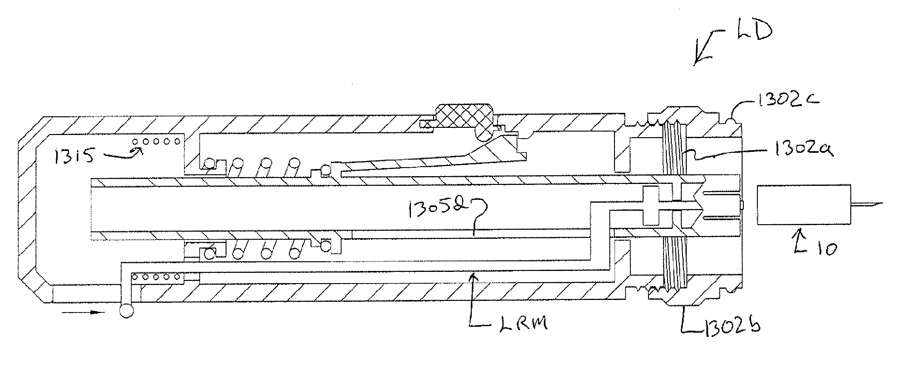
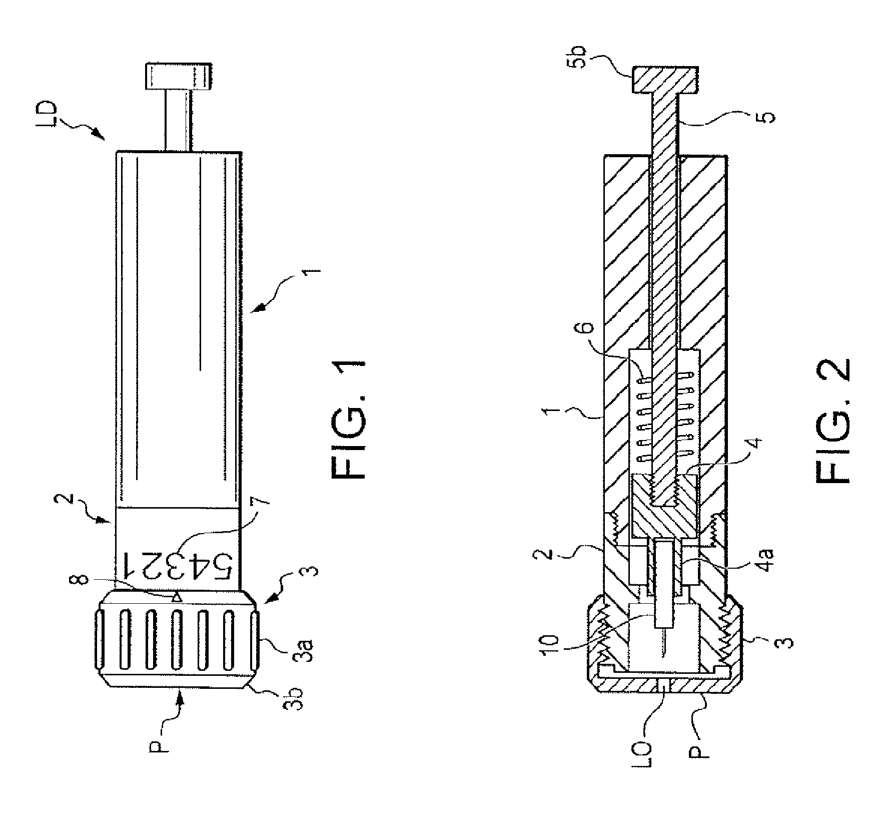
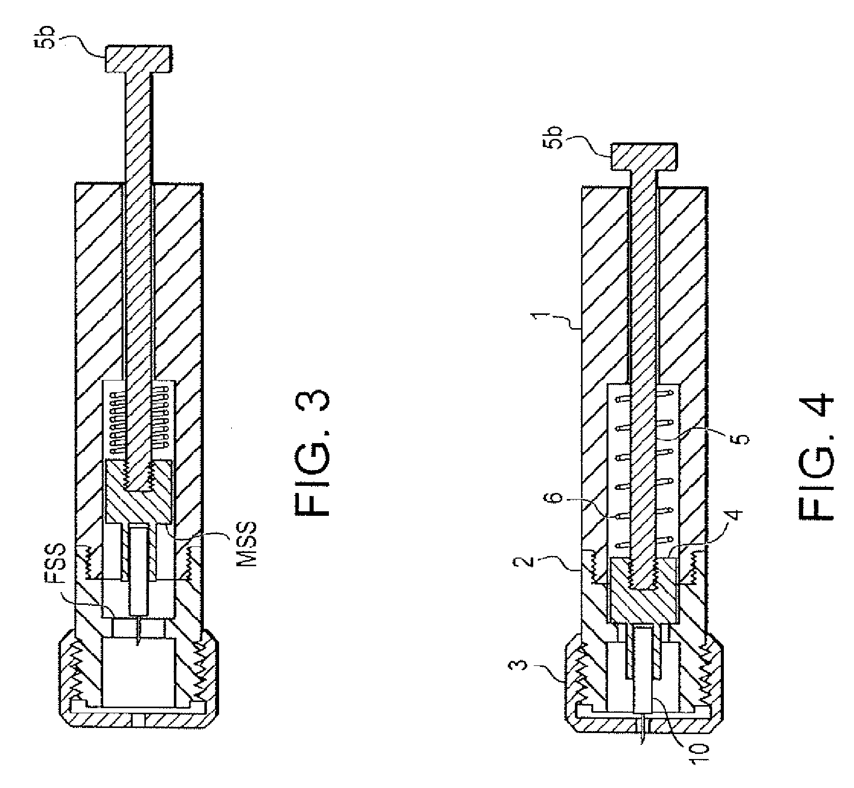
[0169]FIGS. 1-7 show various views of one embodiment of lancet device. Lancet device LD has three main external parts, i.e., a lancet body 1, an intermediate section 2, and a front cover or cap 3. These parts 1, 2 and 3 are connected to each other via threads and / or a threaded connection when the lancet device LD is ini...


PUM


Abstract

Lancet device including a body and a holding member movably mounted within the body and comprising a front end and a rear end. The front end is configured to receive a lancet having the lancet needle. A lancet ejector and/or a biasing member are utilized. The biasing member is one of arranged within the holding member and biasing a mechanism for setting a trigger. This Abstract is not intended to define the invention disclosed in the specification, nor intended to limit the scope of the invention in any way.

Description

CROSS-REFERENCE TO RELATED APPLICATIONS [0001] The present application is a continuation-in-part of U.S. application Ser. No. 11 / 153,381 filed Jun. 16, 2005, the disclosure of which is expressly incorporated by reference herein in its entirety.BACKGROUND OF THE INVENTION [0002] 1. Field of the Invention [0003] The invention relates to a lancet device which is easier, more economical and which is more efficient to make. The invention also relates to a lancet device preferably having an adjusting capability, and a method of using a lancet device. In particular, the invention relates to a lancet device which utilizes an adjustable depth penetration. Lancet devices are used to penetrate and puncture the skin in order to allow the taking of a blood sample for testing. The present device allows the user to control the depth of this penetration by a simple adjustment mechanism. Finally, the lancet device includes an ejector arrangement which allows the user to eject the lancet needle from ...

Claims


Application Information

Patent Timeline
Patent Type & Authority Applications(United States)
IPC IPC(8): A61B17/32
CPCA61B5/1411A61B5/15186A61B5/150198A61B5/150022A61B5/150183A61B5/150259A61B5/150412A61B5/150503A61B5/150587A61B5/150717A61B5/150824A61B5/15113A61B5/15117A61B5/1519A61B5/15194
Inventor SCHRAGA, STEVEN
Owner STAT MEDICAL DEVICES
Why Eureka
Try Eureka