Depressurizing valve and fuel injection device

a technology of depressurizing valve and fuel injection, which is applied in the direction of valve operating means/release devices, machines/engines, etc., can solve the problems of no space for the bolt hole, the air gap would be changed, and it is difficult to form the bolt hole in the common rail

Active Publication Date: 2007-04-19
DENSO CORP
View PDF14 Cites 16 Cited by
  • Summary
  • Abstract
  • Description
  • Claims
  • Application Information

AI Technical Summary

Benefits of technology

[0010] The present invention is made in view of the above problems. An object of the present invention is, therefore, to provide a fuel injection device, more particularly a depressurizing valve mounted to a common rail for the fuel injection device, in which a direction of a connector for the depressurizing valve can be adjusted, without affecting an air gap and a sealing performance.
[0016] In addition, a sealing member (such as an O-ring) is not necessary between the first and second spaces, since the first space for accommodating the valve body and the armature is fluid tightly connected to the second space for accommodating the coil by the connecting member. As a result, it is not necessary to check the sealing performance again after the mounting member is loosened and tightened.
[0022] According to the above feature, the direction of the connector integrally formed with the electromagnetic coil can be adjusted, an air gap formed between the armature and the stator core is not changed, and it is not necessary to check the sealing performance again after the mounting member is loosened and tightened again.
[0023] Furthermore, the number of connecting portions can be reduced, because the connecting member is integrally formed with one of the valve housing and the stator core.
[0028] According to the above feature, the direction of the connector integrally formed with the electromagnetic coil can be likewise adjusted, an air gap formed between the armature and the stator core is not changed, and it is not necessary to check the sealing performance again after the mounting member is loosened and tightened again.
[0033] As a result, any sealing member is not necessary for preventing water from entering into the electromagnetic coil, because the electromagnetic coil and the connector are integrally molded.

Problems solved by technology

However, it is actually difficult to form the bolt hole in the common rail, because the common rail is generally formed as the cylindrical shape, and thereby there is no sufficient space for the bolt hole.
As a result, there would be a problem that the air gap would be changed after the retaining nut was once loosened and then tightly screwed again.
However, there are still problems in that the air gap might be changed and / or the sealing performance should be checked again, as in the fuel injection device of the above mentioned prior art.

Method used


Image

  • Depressurizing valve and fuel injection device
  • Depressurizing valve and fuel injection device
  • Depressurizing valve and fuel injection device

Examples


first embodiment

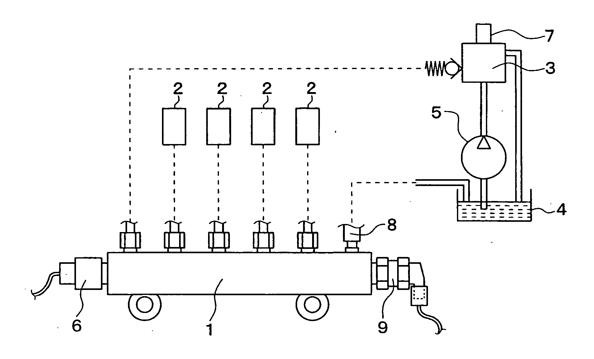
[0043] A first embodiment of the present invention will be disclosed. FIG. 1 is a schematic diagram showing a system structure of a common rail type fuel injection device having a depressurizing valve according to the first embodiment. The fuel injection device has a common rail 1, which is formed into almost a cylindrical shape and in which a high-pressure fuel is stored. Multiple fuel injection valves 2 are connected to the common rail 1, wherein the fuel injection valves 2 are mounted to respective engine cylinders of a diesel engine (not shown) so that the high pressure fuel stored in the common rail 1 is injected into the engine cylinders through the respective fuel injection valves 2. A valve opening timing as well as a valve opening period for the respective fuel injection valves 2 is controlled by an electronic control unit (ECU) which is not shown in the drawing.

[0044] The ECU comprises a well known microcomputer having CPU, ROM, RAM and so on, and carries out various kind...

second embodiment

[0072] A second embodiment of the present invention will be explained. FIG. 5 shows a cross sectional view of the depressurizing valve according to the second embodiment. The same reference numerals are given to the same or similar parts to the first embodiment.

[0073] In the above first embodiment, the coil unit 30 is assembled to the valve unit 10 by the retaining nut 34, wherein the female screw portion 341 of the retaining nut 34 is screwed with the male screw portion 127 of the valve housing 12. The second embodiment differs from the first embodiment in the assembling method of the coil unit 30 to the valve unit 10.

[0074] As shown in FIG. 5, a bolt 35 is used as a fixing means. More exactly, a female screw portion 182 is formed at the stator core 18, a through hole 322 is formed in the connector 32 for inserting the bolt 35, and a through hole 331 is formed in the plate 33 for also inserting a screwed portion of the bolt 35. The bolt 35 can be formed as a hexagon head bolt, a ...

third embodiment

[0076] A third embodiment of the present invention will be explained. FIG. 6 shows a cross sectional view of the depressurizing valve according to the third embodiment. The same reference numerals are given to the same or similar parts to the first embodiment.

[0077] In the first embodiment, the ring-shaped connecting member 17 is used for connecting the valve body 11 to the stator core 18. According to the third embodiment, a pipe-shaped connecting member 17a having a thin wall is used.

[0078] If the connecting member 17 was made of the magnetic material in the first embodiment, the magnetic flux may not flow from the stator core 18 to the armature 13, but flows from the stator core 18 to the valve housing 12 through the connecting member 17. Then, the attracting force is not generated at the armature 13. This is because the connecting member 17 must be made of the non-magnetic material in the first embodiment.

[0079] On the other hand, the connecting member 17a of the third embodi...


PUM


Abstract

An object of the invention is to provide a depressurizing valve mounted to a common rail for a fuel injection device, in which a direction of a connector for the depressurizing valve can be adjusted, without affecting an air gap and a sealing performance. The depressurizing valve has a valve unit and a coil unit which is detachably assembled to the valve unit by a mounting member, such as a retaining nut. A valve housing has an inside space, which is fluid tightly separated into first and second spaces by a connecting member, which is fluid tightly connected to the valve housing and a stator core. A valve body and a spring are arranged in the first space for closing a flow control port. A cylindrical coil is accommodated in the second space, such that the coil is rotatable with respect to the valve housing.

Description

CROSS-REFERENCE TO RELATED APPLICATION [0001] This application is based on Japanese Patent Application Nos. 2005-300318 filed on Oct. 14, 2005 and 2006-186665 filed on Jul. 6, 2006, disclosures of which are incorporated herein by reference. FIELD OF THE INVENTION [0002] The present invention relates to a depressurizing valve for decreasing fuel pressure in a common rail of a fuel injection device at a vehicle deceleration, and further relates to a fuel injection device having the depressurizing valve. BACKGROUND OF THE INVENTION [0003] A conventional fuel injection device for an internal combustion engine has; a common rail for storing a high pressure fuel; fuel injection valves for injecting the high pressure fuel from the common rail into respective cylinders of the engine; a fuel pump for sucking and pressurizing the fuel and supplying the high pressure fuel to the common rail; a fuel return path for returning a portion of the high pressure fuel from the common rail to a low pres...

Claims


Application Information

Patent Timeline
Patent Type & Authority Applications(United States)
IPC IPC(8): F02M59/36
CPCF02M51/005F02M61/168F02M63/0015F02M63/0031F02M63/0052
Inventor NONOYAMA, SHIGERUMITSUMATA, NAOKIMURAKAMI, FUMIAKI
Owner DENSO CORP
Why Eureka
Try Eureka