Cleaning device for internal combustion engine

a cleaning device and internal combustion engine technology, applied in the direction of machines/engines, cleaning using liquids, transportation and packaging, etc., can solve the problems of ineffectiveness of above conventional methods, ineffectiveness, and inconvenient so as to facilitate the control of the flow rate of cleaning solution

Inactive Publication Date: 2007-04-19
CHIANG MEI HUA
View PDF4 Cites 9 Cited by
  • Summary
  • Abstract
  • Description
  • Claims
  • Application Information

AI Technical Summary

Benefits of technology

[0013] Yet another object of the present invention is to provide a cleaning device for internal combustion engine, wherein an adjustable or moveable block plate is provided to change the flowrate of air stream to effect the vacuum therein based on the capacity of the cylinder of the internal combustion engine.
[0014] Yet a further object of the present invention is to provide a cleaning device for internal combustion engine, wherein the guiding tube for leading the cleaning solution is provided with at least an adjusting switch, facilitating the control of the flowrate of the cleaning solution.

Problems solved by technology

However, this conventional method is not effective for cleaning diesel engine.
The above conventional methods are not effective and the drawbacks of these methods are as follows:
This is not economical.
c. There is no air valve in diesel engine and therefore suction force generated by the engine is insufficient, and cleaning solution cannot be introduced into the air inlet manifold to clean the air-inlet manifold.
If the speed of the engine is lifted in order to increase the suction force, the cylinder will probably explode.

Method used


Image

  • Cleaning device for internal combustion engine
  • Cleaning device for internal combustion engine
  • Cleaning device for internal combustion engine

Examples


Embodiment Construction

[0024] The following descriptions are of exemplary embodiments only, and are not intended to limit the scope, applicability or configuration of the invention in any way. Rather, the following description provides a convenient illustration for implementing exemplary embodiments of the invention. Various changes to the described embodiments may be made in the function and arrangement of the elements described without departing from the scope of the invention as set forth in the appended claims.

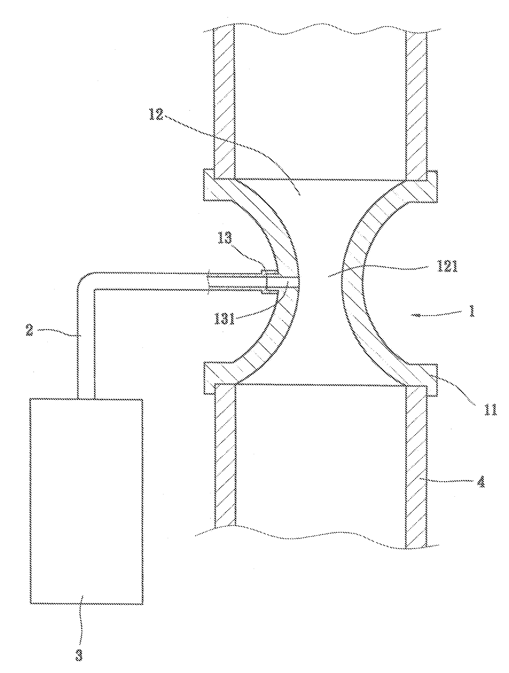
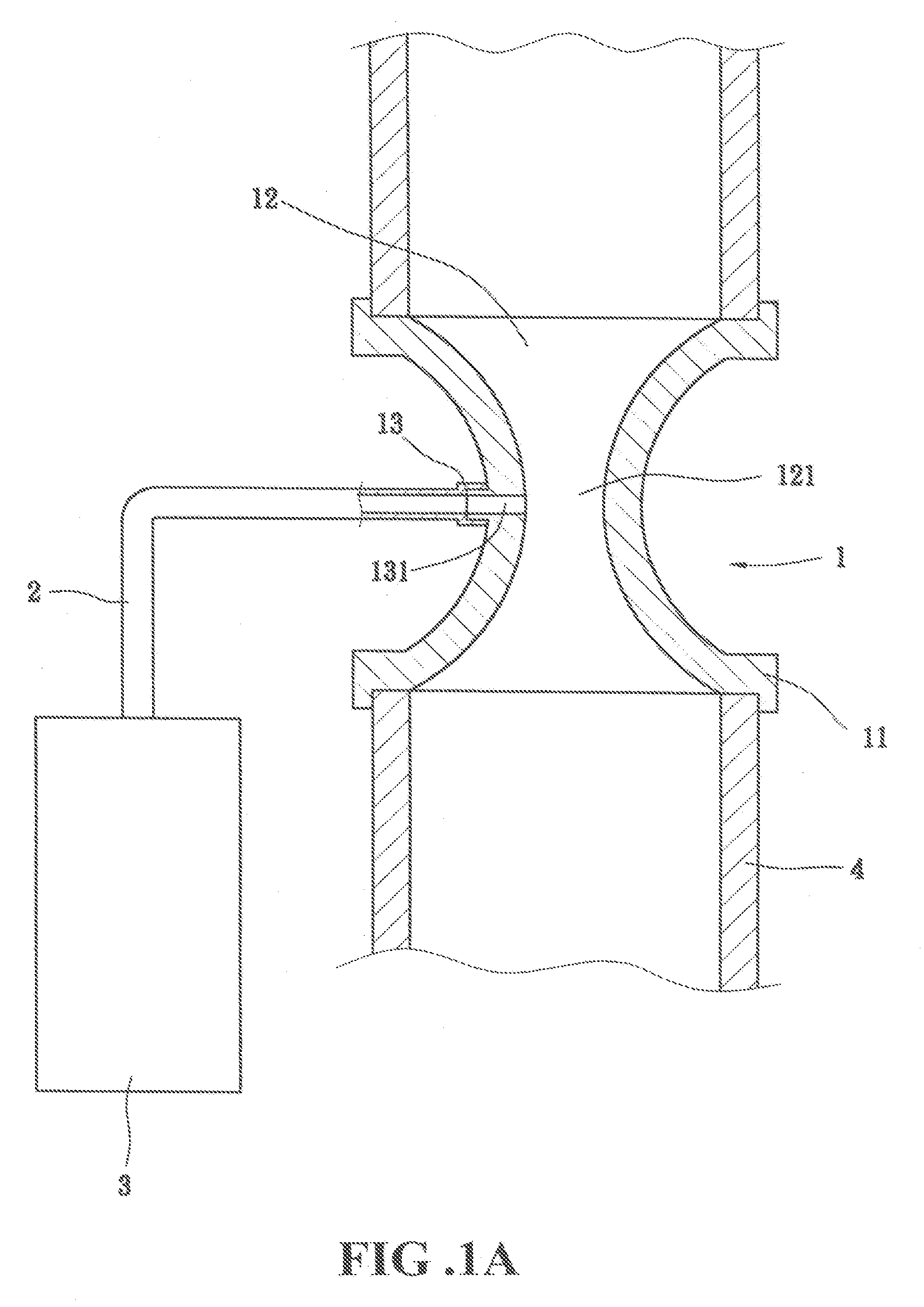
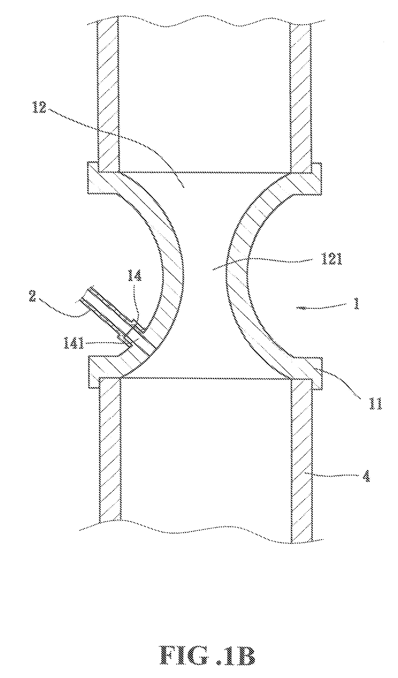
[0025] Referring to FIGS. 1A, 1B and 1C, there is shown a first preferred embodiment in accordance with the present invention. The cleaning device comprises a container 3 for storing a cleaning solution, a suction generator 1 connected to an air-inlet tube 4 of the internal combustion engine. One end portion of the suction generator 1 is mounted with a connecting section 11 for mounting to the end section of the air-inlet tube 4 or the middle section of the air-inlet tube 4. The interior of the...


PUM


Abstract

A cleaning device for internal combustion engine by way of suction force generated at the air-inlet tube of the engine is disclosed. The tapered air passage accelerates the air stream to produce a suction force, or a moveable or adjustable valve device to change the surface area of the air passage so as to control the effect of vacuum, and the cleaning solution is sucked into the air-inlet tube to clean away the accumulated carbon and debris in the valves or the internal combustion engine.

Description

CROSS-REFERENCE [0001] This is a division of the co-pending patent application Ser. No. 10 / 647,312, filed Aug. 26, 2003.BACKGROUND OF THE INVENTION [0002] (a) Technical Field of the Invention [0003] The present invention relates to a cleaning device, and in particular, a cleaning device for internal combustion engine by way of a suction force generated at an air-inlet tube to the engine and by controlling the suction force to withdraw a cleaning solution into the internal combustion engine to clean the accumulated carbon and the like debris accumulated therein. [0004] (b) Description of the Prior Art [0005] After a period of operation of an internal combustion engine, carbons and / or the like materials are accumulated at tubes or conduits or cylinders of the internal combustion engine. Therefore, it is an indispensable step to remove the accumulated carbons and debris or to clean away the accumulated carbons. [0006] Conventional ways of cleaning the internal combustion engine is by u...

Claims


Application Information

Patent Timeline
Patent Type & Authority Applications(United States)
IPC IPC(8): B08B3/02
CPCB01F5/0413B01F5/0428B08B9/00F02B77/04B01F25/312B01F25/31242
Inventor CHIANG, MEI-HUA
Owner CHIANG MEI HUA
Why Eureka
Try Eureka