
Twist-on wire connector

a twist-on wire and connector technology, applied in the direction of cable junctions, connection end caps, coupling devices, etc., can solve the problems of finger pain, slippage of the shell surface, and small benefit, so as to inhibit finger and hand injury and fatigue

Active Publication Date: 2007-04-19
THE PATENT STORE
View PDF2 Cites 5 Cited by
  • Summary
  • Abstract
  • Description
  • Claims
  • Application Information

AI Technical Summary

Benefits of technology

[0010] Briefly, the invention comprise a twist-on wire connector having a free standing cover that extends over the normal hand gripping region and at least part or all of the normal non-hand gripping region of the twist-on wire connector so that regardless of the manner the twist-on wire connector is grasped the user fingers engage a resilient cover to inhibit finger and hand injury and fatigue from repeated securement of twist-on wire connectors to electrical leads.
[0011] The present invention provides an improved twist-on wire connector wherein the entire exterior portion of the shell, which might come into contact with the users hand or fingers, comprises a resilient grip that has multiple degrees of responsiveness to finger pressure. That is, the cover can resiliently compress radially inward to accommodate squeezing pressure from the user's fingers and can circumferentially and axially deflect through the shear resistance of the material to thereby comfortably accommodate the lateral twisting forces on the external surface regions of the cover. Consequently, for those persons who do not grasp the twist-on wire connector on the designated hand gripping regions or those users who normally grasp the wire connector on the designated hand gripping regions but because of cramped conditions or personal preferences, which require them to grasp only the end section of the wire connector, can now have the benefit of a cushioned grip for their fingers regardless of how they have to grasp the twist-on wire connectors during the connection process.
[0012] A further feature of the invention is the surface securement of the finger friendly cover to the wire connector hard shell which allows one to retain the inherent characteristics of the resilient cover since internal forces are not introduced into the cover as a result of securement of the cover to the wire connector.
[0013] A further feature is that the use of a cushioned cover over the entire exterior portion of the shell that a user's fingers can come into contact with provides an added benefit as the cushioned covered twist-on wire connector is pushed back into the junction box. That is, the exterior surface of the twist-on wire connector can contact or rub against the insulation on the electrical wires as the wire connector is forced into the junction box. With the use of a resilient material or cushioned cover on the exterior surface of the twist-on wire connector it reduces or inhibits the opportunity to accidentally damage the insulation on the other wires if the twist-on wire connector contacts or rub against the electrical insulation on the other wires.
[0015] A further benefit is that the cushioned cover on the exterior portion of the shell can provide extra electrical insulation. That is, in certain applications one may want to handle higher voltages. With the exterior portion of the shell covered with a resilient material that has enhanced electrical insulating qualities one can provide a twist-on wire connector suitable for a wider range of voltages.
[0016] A further benefit is that wire connectors having heat shrinkable materials on the hard shell of the wire connector can also be made finger friendly. That is, the biased of the heat shrunk material can be overcome by placing a layer of surface secured resilient material over the heat shrunk material to form a cushioned cover over the heat shrunk material.

Problems solved by technology

Blaha points out the problem of installing twist-on wire connectors with a hard shell is that if numerous connections are made the hard plastic surface can be painful on the fingers or in certain instances the shell surface can be slippery due to the sweat or soil on the users hand.
While Blaha recognizes that the placement of cushion grip on the grip mounting portion of the twist-on wire connector can reduce fatigue Blaha does not recognize that not everyone grasps the twist-on wire connectors in the same manner or that because of cramped conditions it might not be possible to grasp the twist-on wire connector on the grip mounting portions to enable the user to benefit from the cushioned grip of Blaha.
Consequently, while the Blaha twist-on wire connector has a cushioned grip it can be of little benefit to those users who do not grip the twist-on wire connector on the normal designated gripping portions or those user who might have to apply a twist-on wire connector in a location with inadequate space to position the users hand or fingers around the normal hand gripping regions of the twist-on wire connector.
Thus, when application conditions are the most difficult one not only does one not have the benefit of cushioned grip for the users fingers but one has to generate greater hand force on the twist-on wire connector to obtain the necessary torque to bring the wire connector into engagement with the electrical wires therein.
However, Krup fails to teach the vinyl shell located around his rigid cage comprises a cushioned surface.
Unfortunately, tightly shrinking the material around the body of connector introduces a circumferential bias or tension force in the heat shrunk material thus rendering material which may even be soft into a covering that is hard to the touch and is reluctant to yield to finger torque.
Thus the heat shrunken tube on the body of his wire connector produces an external surface that resists resilient displacement and is also hard and is uncomfortable in response to the finger and hand pressure of the user since the tension and bias forces introduced by the heat shrinking limit the yielding of his material.
The effect is to form an elastomer material into a hard cover or non resilient cover on a hard shell since a heat shrunk cover is limited in its ability to absorb external finger pressure.

Method used


Image

  • Twist-on wire connector
  • Twist-on wire connector
  • Twist-on wire connector

Examples


Embodiment Construction

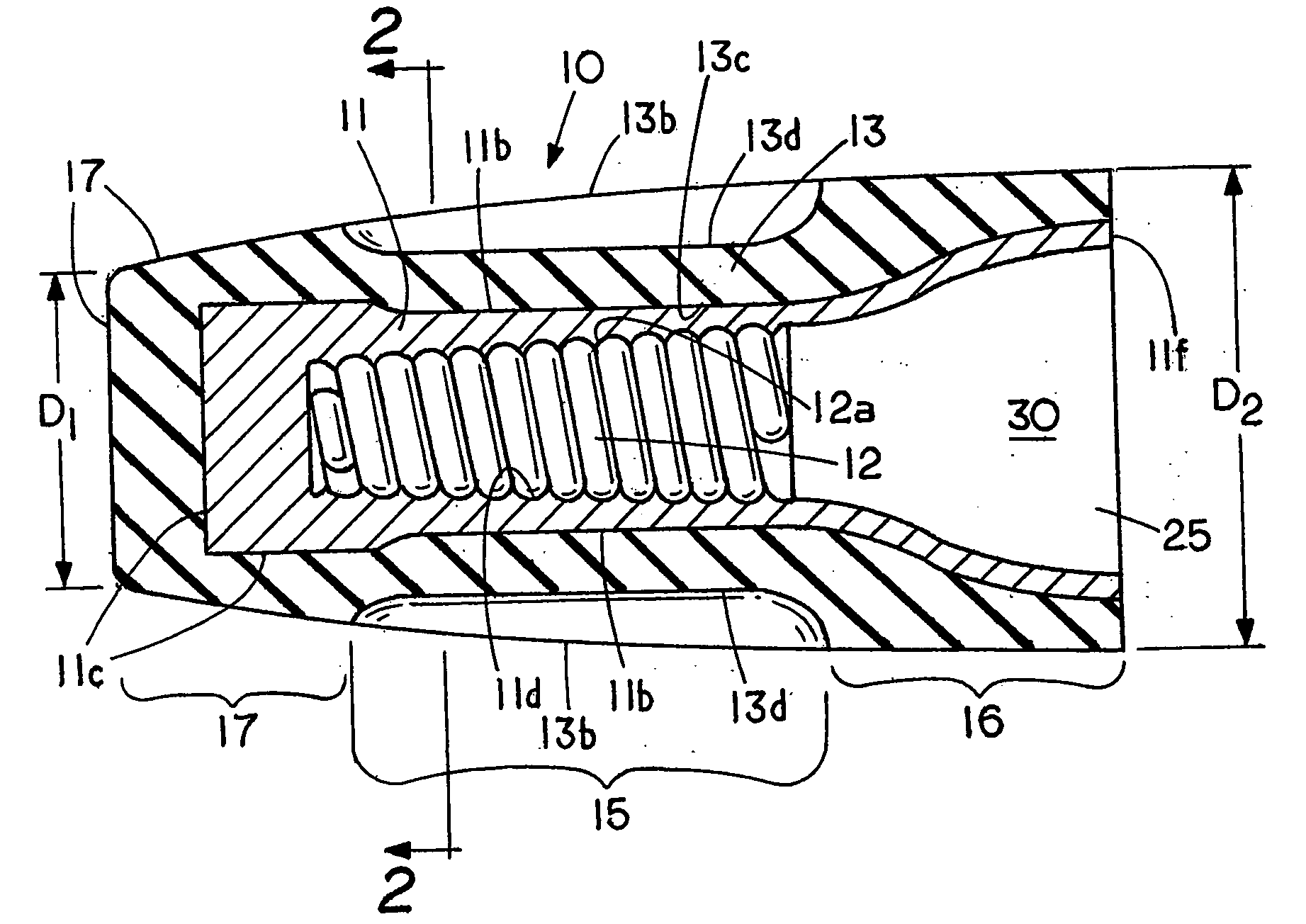
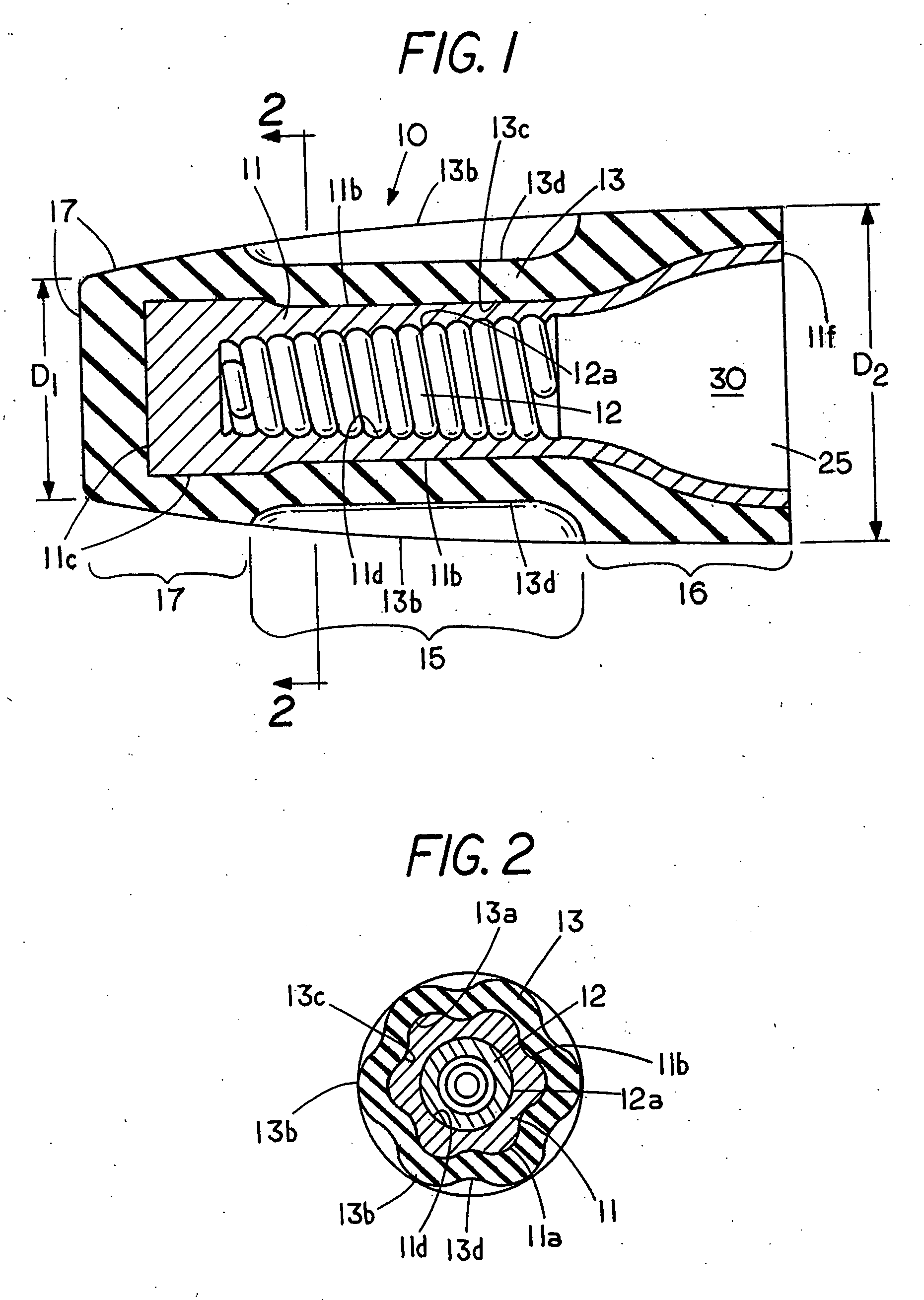
[0044] Referring to the drawings, FIG. 1 shows a cutaway view of a wingless, twist-on wire connector 10 having a closed end an open end for insertion of electrical wires therein and FIG. 2 shows a section view taken along lines 2-2 of FIG. 1.

[0045] Wire connector 10 includes a rigid internal shell 11 with an open end 25 and a closed end, the shell having an interior surface 11d for engagement with wire coil 12 and an overmolded soft shell or cushioned cover 13 with a closed end an open end 25. The hard shell 11 is conventionally used on the exterior of twist-on wire connectors and usually contains ribs, reliefs, grooves or wings to enhance the users grip of the twist-on wire connector. That is, to apply a twist-on wire connector the user rotates the twist-on wire connector with one hand while the wires are held firmly in the other hand. The result is that the wire ends are twisted into electrical engagement with each other in the spiral thread of the twist-on wire connector.

[0046]...


PUM


Abstract

A twist-on wire connector having a finger friendly unbiased cushioned cover that covers not only the normal hand gripping region but at least part or all of the normal non-hand gripping region of the twist-on wire connector so that regardless of the way the twist-on wire connector is grasped the user fingers engage the cushioned cover to inhibit finger and hand injury and fatigue from repeated securement of twist-on wire connectors to electrical leads and a method of making a twist-on wire connector with a cushioned cover by placing a soft to the touch material on the exterior surface of the twist-on wire connector.

Description

CROSS REFERENCE TO RELATED APPLICATIONS [0001] This application is a continuation in part of U.S. patent application Ser. No. 11 / 249,868 filed Oct. 13, 2005 titled Cushioned Wire Connector.FIELD OF THE INVENTION [0002] This invention relates generally to twist-on wire connectors and, more specifically, to a finger friendly twist-on wire connector that provides three-axis deflection regardless of the users finger position. STATEMENT REGARDING FEDERALLY SPONSORED RESEARCH OR DEVELOPMENT [0003] None REFERENCE TO A MICROFICHE APPENDIX [0004] None BACKGROUND OF THE INVENTION [0005] The concept of twist-on wire connector with a cushioned grip is known in the art, more specifically Blaha U.S. Pat. No. 6,677,530 discloses numerous embodiments of twist-on wire connectors and points out that the cushioned grip is on a portion of the exterior hard shell with the cushioned grip being an olefinic thermoplastic vulcanizate sold under the name Santoprene®, a trademark of Advanced Elastomer system ...

Claims


Application Information

Patent Timeline
Patent Type & Authority Applications(United States)
IPC IPC(8): H01R4/00
CPCH01R4/22H01R13/631H01R43/26
Inventor KING, LLOYD HERBERT JR.BELGERI, MICHAELKEEVEN, JAMES C.VLASATY, FRANKHINER, WILLIAM
Owner THE PATENT STORE
Learn More