RFID tag incorporating at least two integrated circuits

a technology of integrated circuits and radio frequency identification, applied in the direction of burglar alarm mechanical actuation, burglar alarm by hand-portable articles removal, instruments, etc., can solve the problem of negligible failure probability, achieve the effect of minimizing inter-chip interference, increasing power or gain, and increasing the ability of microradio chips to work together

Active Publication Date: 2007-04-19
RADIOFIDO
View PDF13 Cites 48 Cited by
  • Summary
  • Abstract
  • Description
  • Claims
  • Application Information

AI Technical Summary

Benefits of technology

[0018] If in addition, during the programming of the multiple integrated circuit microradio chips, one can correct for polarization reversals, then the ability of the microradio chips to work together is increased due to the identical polarization directions of the microradio chips, which minimizes inter-chip interference.
[0019] Further, during programming it is possible to activate only those integrated circuit microradio chips that are tightly coupled to the tag antenna, again increasing power or gain.
[0020] Finally, as a result of the ink jet fabrication techniques involving deposit of multiple microradio chips at an antenna feed point, costly pick-and-place machines are avoided.
[0021] In short, the use of more than one integrated circuit microradio chip at the feed point of an RFID tag antenna significantly reduces the cost of the RFID tags and does not involve pick-and-place machines, which are expensive. The use of large numbers of microradio chips also completely eliminates the requirement for testing. Additionally, due to the use of multiple integrated circuit microradio chips working in concert, one has greater reliability, more output power, greater range and / or better bit error rates depending on the tradeoffs involved.
[0022] In summary, multiple RFID integrated circuit microradio chips are located at the feed point of an RFID tag antenna for greater reliability, elimination of testing and to take advantage of coherent microradio operation for increased gain and power, better signal-to-noise ratios, improved range and low bit error rates. Having large numbers of integrated circuit microradio chips at the feed point of an RFID tag antenna, when coheretized, polarization controlled and orientation-controlled results in a low-cost RFID tag in which no pick-and-place costs are necessitated and in which testing requirements are eliminated. The provision of multiple integrated circuit microradio chips also results in better reliability, more power, greater range and better bit error rates.

Problems solved by technology

This is because, when using hundreds or thousands of microradios at the feed point of the antenna, the probability of failure when raised to the n power results in a negligible failure probability.

Method used


Image

  • RFID tag incorporating at least two integrated circuits
  • RFID tag incorporating at least two integrated circuits
  • RFID tag incorporating at least two integrated circuits

Examples


Embodiment Construction

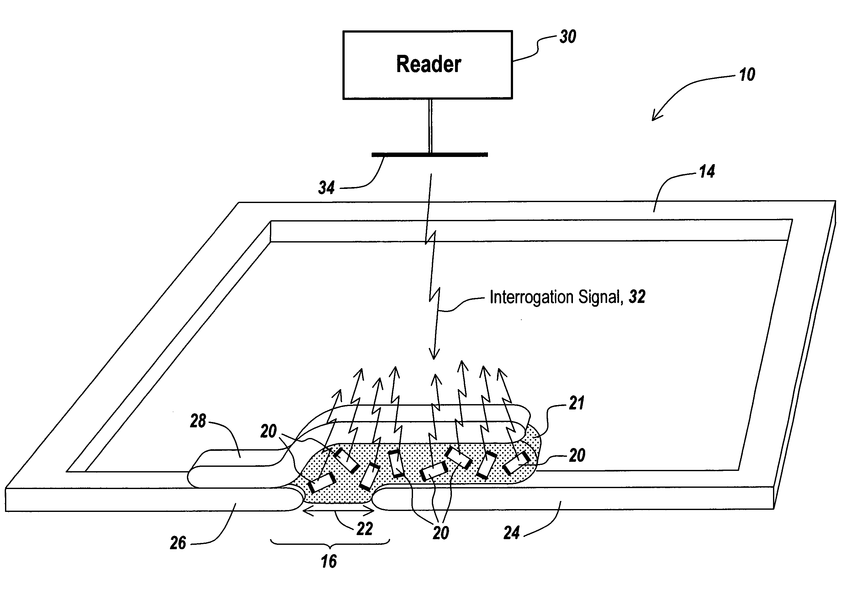
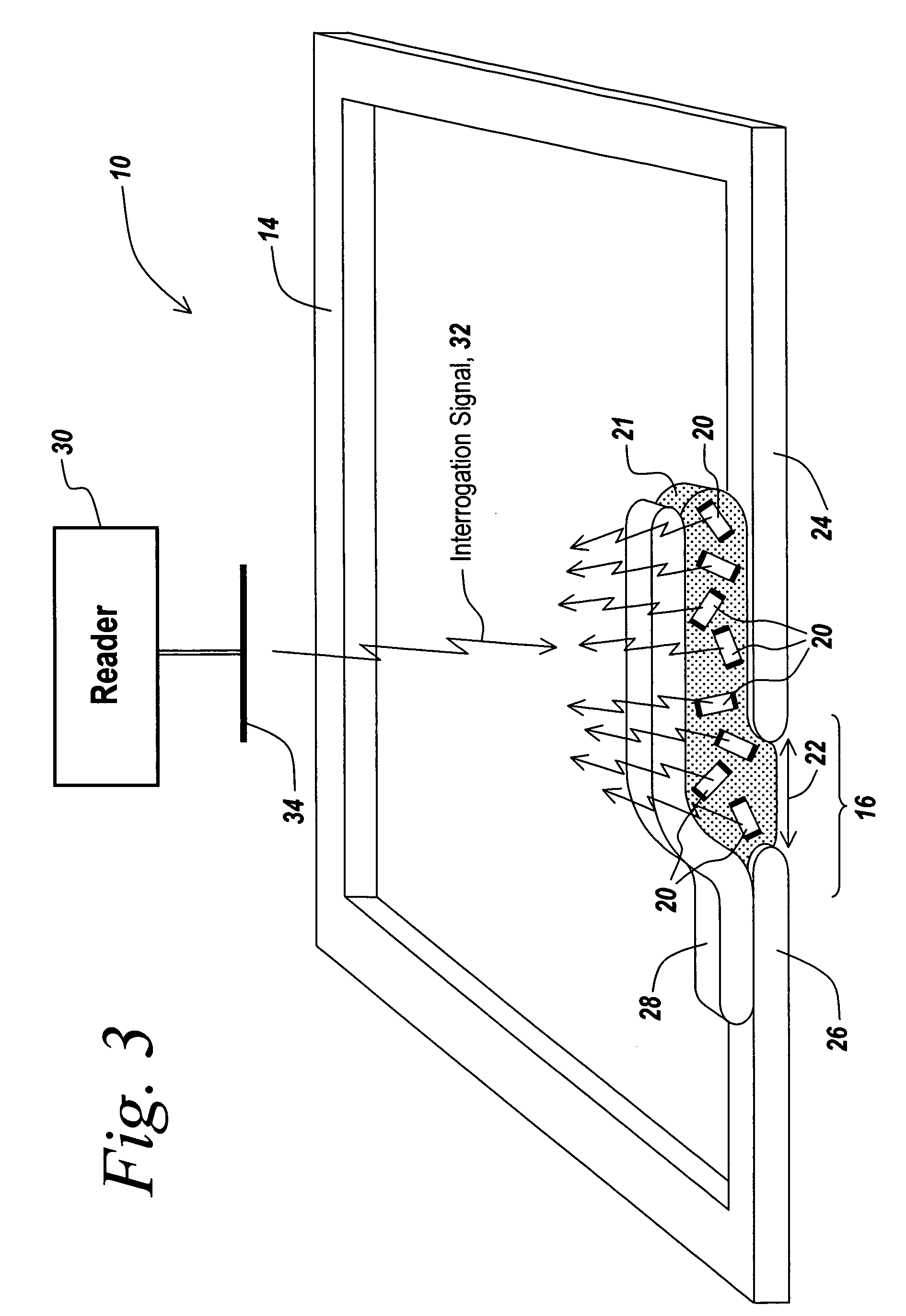
[0032] By way of further background, radio Frequency Identification (RFID) tags have been utilized extensively to trace pallets of merchandise from a point of shipment to a final destination. The tags are typically passive devices that are read out with RF energy, usually in the 900 MHz range. These passive devices are parasitically powered by the RF energy impinging upon the antenna of the tag, thus powering the integrated circuits within the tag, with the result that the tag transmits the identity of the pallet in response to a probing signal from a reader in the vicinity of the tag.

[0033] While such RFID tags are now mandated for pallets in some industries, there is increased level of interest in item-level tagging, which involves placing a tag on the item itself as opposed to on a pallet of items.

[0034] However, in order to be able to make such tagging strategies possible for low-value items such as toothpaste and the like, techniques are required to be able to manufacture and...


PUM


Abstract

Multiple RFID integrated circuit microradio chips are located at the feed point of an RFID tag antenna for greater reliability, elimination of testing and to take advantage of coherent microradio operation for increased gain and power, better signal-to-noise ratios, improved range and low bit error rates.

Description

RELATED APPLICATIONS [0001] This Application claims rights under 35 USC § 119(e) from U.S. Provisional Application Ser. No. 60 / 726,145 filed Oct. 13, 2005, the contents of which are incorporated herein by reference. This application is related to PCT Patent Applications: US2006 / 033,111 filed Aug. 24, 2006 by Kenneth R. Erikson, entitled “RFID Tag and Method and Apparatus for Manufacturing Same;” US2006 / 033,048 filed Aug. 24, 2006 by Court Rossman, Zane Lo, Roland Gilbert and John Windyka, entitled “Methods for Coupling an RFID Chip to an Antenna;” US2006 / 033,049 filed Aug. 24, 2006 by Steve A. Hedges and Kenneth R. Erikson, entitled “Method and Apparatus For Coupling Multiple Microradios To an RFID Tag Antenna;” US2006 / 033,112 filed Aug. 24, 2006 by Karl D. Brommer and Kenneth R. Erikson, entitled “Coherent Multichip RFID Tag and Method and Apparatus for Creating such Coherence;” and US2006 / 024,630, filed Jun. 23, 2006 by Daniel N. Carothers and entitled “CMOS Process for Fabricatio...

Claims


Application Information

Patent Timeline
Patent Type & Authority Applications(United States)
IPC IPC(8): G08B13/14G06K19/06
CPCG06K19/072G06K19/07749
Inventor BROMMER, KARL D.ERIKSON, KENNETH R.BUTLER, TIMOTHY P.
Owner RADIOFIDO
Why Eureka
Try Eureka