Probe observing device and surface texture measuring device

a technology of surface texture and observing device, which is applied in the direction of measurement device, instruments, computing, etc., can solve the problems of reducing measuring efficiency, difficult to adjust the probe to enter the view field of the video camera, and difficulty in visually observing the probe with a naked eye, so as to save measurement work, simplify the operation, and high degree of accuracy

Inactive Publication Date: 2007-04-19
MITUTOYO CORP
View PDF5 Cites 16 Cited by
  • Summary
  • Abstract
  • Description
  • Claims
  • Application Information

AI Technical Summary

Benefits of technology

[0008] The present invention has an object to provide a probe observing device and a surface texture measuring device which are capable of observing a probe with high measuring accuracy through simple operation.

Problems solved by technology

Therefore, it has become difficult to visually observe a probe with a naked eye.
In this case, however, the view field of the video camera narrows as the magnification of the magnifier increases, making it difficult to adjust the probe to enter the view field of the video camera.
Accordingly, there arises a problem in that it is also time-consuming to adjust the probe and the camera such that the probe enters the view field of the camera, which reduces measuring efficiency.
On the other hand, adoption of a low-magnification magnifier naturally makes it easy to adjust the probe to enter the view field of the video camera, whereas the close observation of the precision probe cannot be attained with the low-magnification magnifier.
Therefore, there arises another problem in that it is impossible to accurately bring the probe to the measuring point, which reduces measuring accuracy.

Method used


Image

  • Probe observing device and surface texture measuring device
  • Probe observing device and surface texture measuring device
  • Probe observing device and surface texture measuring device

Examples


Embodiment Construction

[0044] Hereinafter, an embodiment of the present invention is explained with reference to the drawings and reference numerals denoting elements in the drawings.

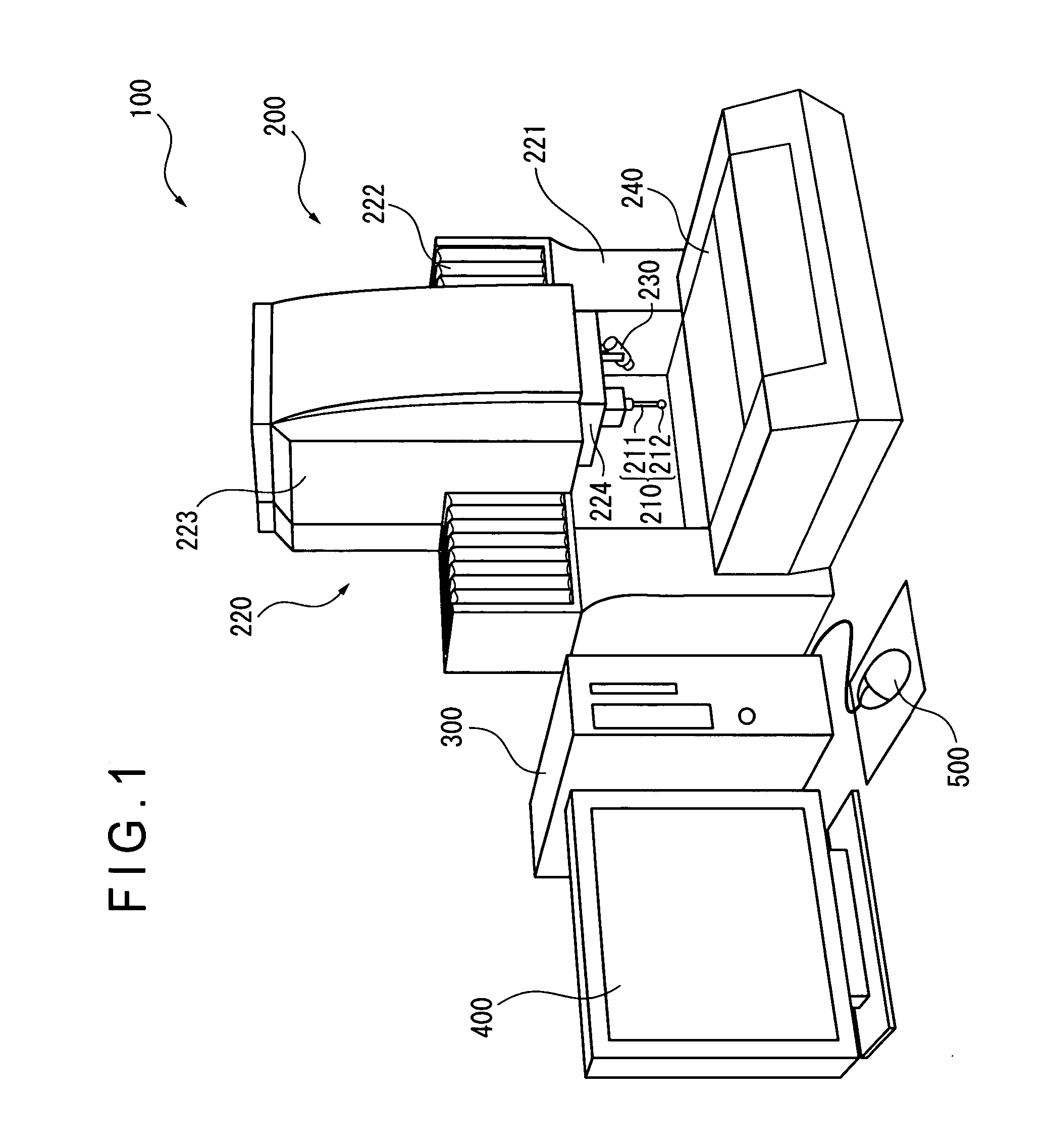
[0045]FIG. 1 is a diagram showing an entire configuration of a surface texture measuring device 100.

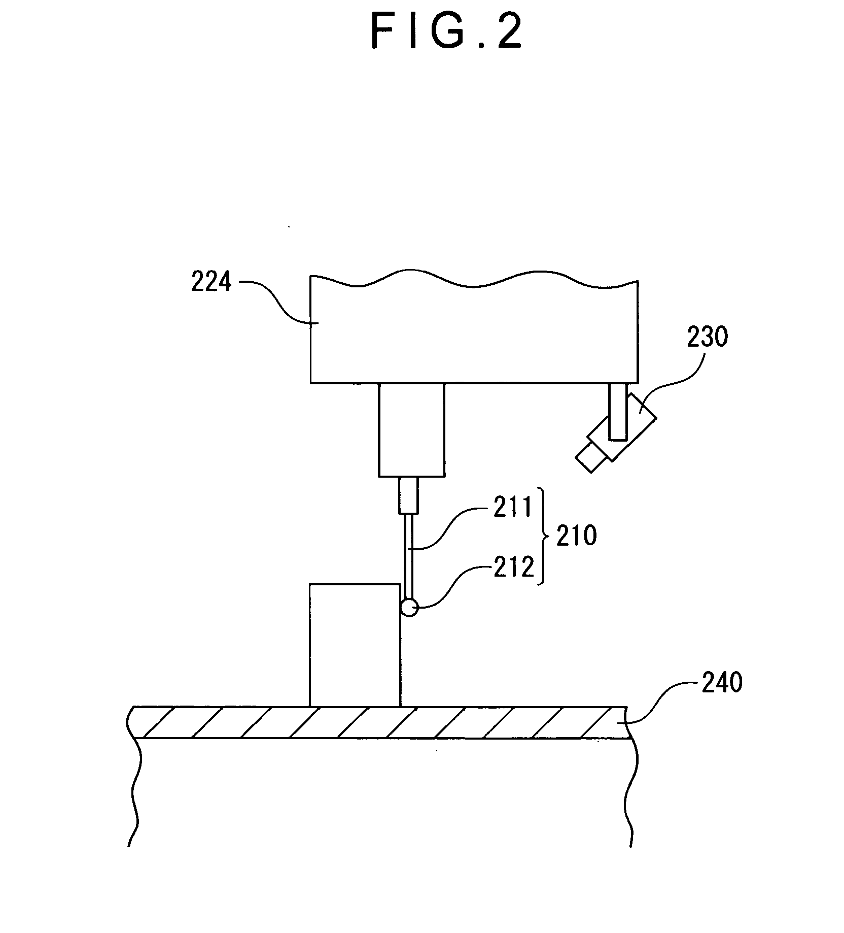
[0046]FIG. 2 is a diagram showing a state where an image of a probe 210 is taken by a camera 230.

[0047] The surface texture measuring device 100 includes: a measuring device main body 200; a central control unit 300; a monitor (i.e., display) 400; and a mouse (i.e., operating device) 500. The measuring device main body 200 includes the probe 210 capable of moving three-dimensionally and a camera (i.e., image taking device) 230 for observing the probe 210. The central control unit 300 controls operation of the measuring device 200 and processes image data on an image taken by the camera 230. The monitor 400 displays measurement data and image data. The mouse 500 is used by a user to input an operation instruction through manu...


PUM


Abstract

Provided is a probe observing device, including: a camera (230) for taking an image of a probe (210 ); an image processing unit (330) for processing data on the image taken by the camera (230); a monitor (400) for displaying the image data processed by the image processing unit (330); and a mouse (500) for inputting an instruction for image processing through manual operation. The image processing unit (330) includes an image data processing unit (350) for processing the image data in accordance with the instruction inputted by the mouse. The camera (230) includes a low-magnification lens system, and is provided to be fixed in position with respect to the probe (210) such that the probe (210) enters the view field of the camera (230).

Description

BACKGROUND OF THE INVENTION [0001] 1. Field of the Invention [0002] The present invention relates to a probe observing device and a surface texture measuring device. The present invention relates to, for example, a probe observing device for observing a probe used in measuring a surface texture of an object to be measured by using a monitor or the like. [0003] 2. Description of Related Art [0004] There has been known a surface texture measuring device for measuring a surface texture or a three-dimensional profile of an object to be measured by scanning the object surface to be measured. Examples of such the surface texture measuring device include a roughness measuring machine, a counter measuring machine, a roundness measuring machine, and a coordinate measuring machine. The surface texture measuring device employs a probe for detecting the object surface to be measured. In recent years, in response to an increasing demand for an extremely high measuring accuracy along with the use...

Claims


Application Information

Patent Timeline
Patent Type & Authority Applications(United States)
IPC IPC(8): G06K9/00
CPCG01B5/008G01B11/007
Inventor ARAI, MASANORI
Owner MITUTOYO CORP
Why Eureka
Try Eureka