Laser marking device, laser marking method, and object to be marked

a laser marking and laser marking technology, applied in the field of laser marking devices and laser marking methods, can solve the problems of inferior durability, inferior visibility, and the inability to apply sole polycarbonate to products such as cards, and achieve the effect of easy and clear marking an imag

a laser marking and laser marking technology, applied in the field of laser marking devices and laser marking methods, can solve the problems of inferior durability, inferior visibility, and the inability to apply sole polycarbonate to products such as cards, and achieve the effect of easy and clear marking an imag

US20070086822A1Inactive Publication Date: 2007-04-19ARAI HELMET LTD

Image

  • Laser marking device, laser marking method, and object to be marked
  • Laser marking device, laser marking method, and object to be marked
  • Laser marking device, laser marking method, and object to be marked

Examples


Embodiment Construction

[0049] A description will now be given of an embodiment of the present invention with reference to drawings. It should be noted that members, arrangements, configurations, and the like described later are not intended to limit the present invention, and will be modified in various ways within a purport of the present invention.

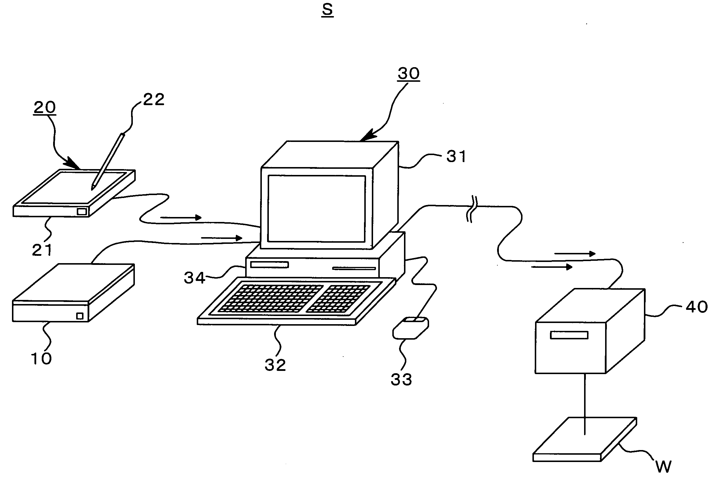
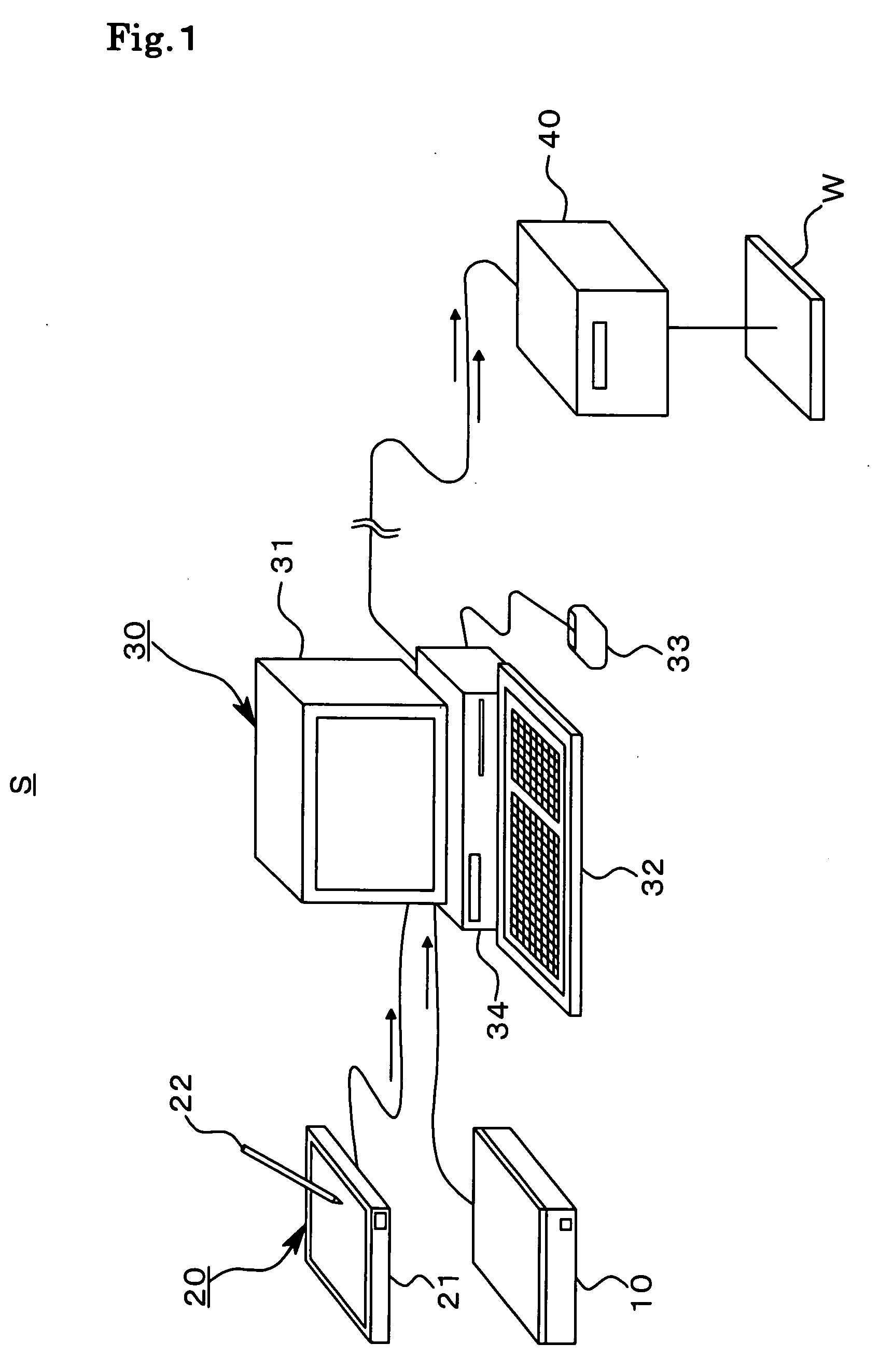
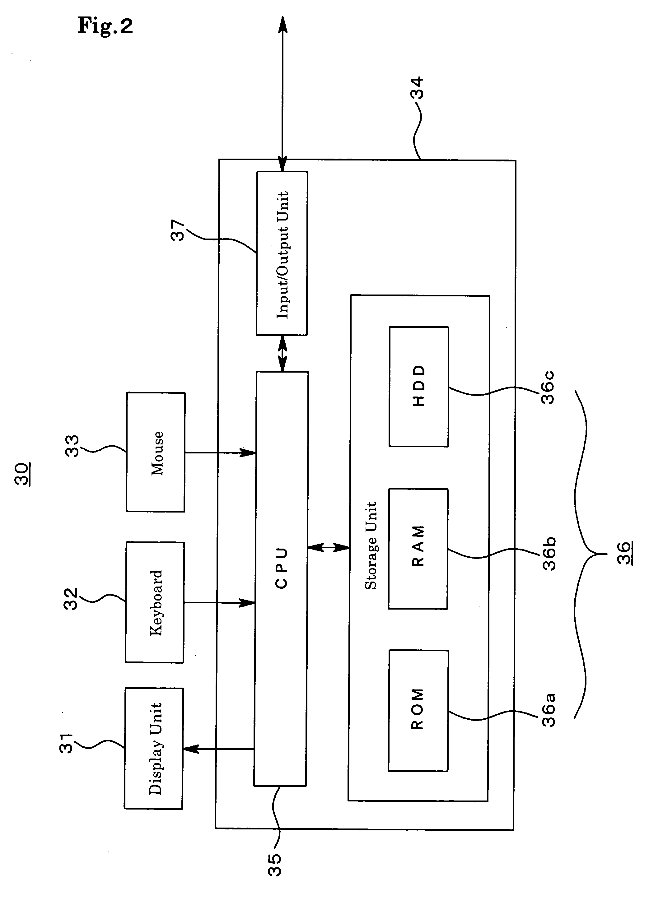
[0050] FIGS. 1 to 11 are views showing embodiments of the present invention in which: FIG. 1 is a view describing an overall configuration of a laser marking device, FIG. 2 is a diagram describing a configuration of a data control unit, FIG. 3 is a diagram describing a configuration of a laser marker, FIG. 4 is a flowchart showing a process of a laser marking method according to the present embodiment, FIG. 5 is a cross sectional view of a card having a three-layer structure, FIG. 6 is a view describing a marking depth upon inside marking performed for the card having the three-layer structure, FIG. 7 is a view describing trajectories of a laser beam which ha...


PUM

PropertyMeasurementUnit
thicknessaaaaaaaaaa
thicknessaaaaaaaaaa
areaaaaaaaaaaa

Abstract

The present invention relates to a laser marking device that irradiates a laser beam on a workpiece (W) to transform a portion inside the workpiece at a focal point of the laser beam, thus putting a dot in each predetermined area. The laser marking device includes acquiring means (10, 20) that acquires, as information on the dot, at least two-dimensional position information of an exposed section of the workpiece (W), and density information of the dot, coordinate setting means (30) that calculates, for each dot according to the density information, dot depth information showing the distance from the surface of the workpiece (W) to the dot in the thickness direction of the workpiece (W), and sets three-dimensional coordinates for each dot based on a position specified by the dot depth information and the two-dimensional position information, and laser marking means (40) that performs marking with the three-dimensional coordinates as a laser beam focal point.

Description

TECHNICAL FIELD [0001] The present invention relates to a laser marking device, a laser marking method, and an object to be marked, and more particularly relates to a laser marking device, a laser marking method, and an object to be marked which can adjust the density of an image and the like to be marked, and can perform marking which causes marked two-dimensional codes, characters, logo marks, images, and the like to appear clearly and three-dimensionally hovering. BACKGROUND ART [0002] There has been known a conventional technology which uses a marking device to mark two-dimensional codes, characters, logo marks, images, and the like on a transparent polycarbonate material. [0003] The polycarbonate is a transparent material in a pure state, and is generally excellent in shock resistance, weather resistance, electrical insulation, dimensional stability, and the like. [0004] A conventional method to mark characters and the like on the polycarbonate often employs inkjet printing. [0...

Claims


Application Information

Patent Timeline
19 Apr 2007
Publication
US20070086822A1
IPC
B41J3/38; B23K26/00; B32B27/00; G06K1/12
CPC
B23K26/0639; B23K26/0643; B23K26/0648; B23K26/0665; B23K26/362; B23K2201/18; B23K2201/34; B23K2201/36
Inventors
SATO, KAZUO