Continuous gas flow trocar assembly

a gas flow and assembly technology, applied in the field of medical devices, can solve the problems of affecting the removal of instruments or any tissue, affecting the removal of instruments, and certain seals only working for a limited range of instrument diameters

Inactive Publication Date: 2007-04-19
SURGIQUEST
View PDF10 Cites 27 Cited by
  • Summary
  • Abstract
  • Description
  • Claims
  • Application Information

AI Technical Summary

Benefits of technology

[0025] The invention may include a method of sealing a trocar assembly within a cavity of a patient during a surgical procedure by an instrument within that cavity of the patient, comprising: introducing a pressurized air through a plenum in the trocar assembly to form a wall of air within the cavity of the patient to seal the cavity from excessive loss of air pressure within the cavity of the patient; piercing the wall of air by the instrument during the surgical procedure; maintaining a generally constant pressure within the cavity of the patient by supplying a constant flow of pressurized air through the plenum in the trocar assembly and into the cavity of the patient; manipulating the medical instrument with respect to the trocar assembly in the absence of interference by the trocar assembly with the instrument.
[0026] The invention may also include a surgical method including the steps of piercing the wall of air by the instrument during the surgical procedure; maintaining a generally constant pressure within the cavity of the patient by supplying a constant flow of pressurized air through the plenum in the trocar assembly and into the cavity of the patient; manipulating the medical instrument with respect to the trocar assembly in the absence of interference by the trocar assembly with the instrument, wherein a spiral groove may be arranged on an inner surface of an inner tubular member of the assembly; arranging a duckbill type valve at a proximal location of the inner tubular member to minimize splashing of exiting gas and liquid thereat;

Problems solved by technology

However when the instrument is retracted, such a trap door or valve may interfere with the removal of the instrument or any tissue being transported thereby.
Certain problems arise with the types of seals utilized in these trocar devices.
Certain seals only work for a limited range of instrument diameters.
Typically the seals do not last through any procedures because they are subject to wear and tearing.
Those prior art seals also may often interfere with the removal of the instrument and / or any tissue being withdraw from the patient utilizing that particular instrument.

Method used


Image

  • Continuous gas flow trocar assembly
  • Continuous gas flow trocar assembly
  • Continuous gas flow trocar assembly

Examples


Embodiment Construction

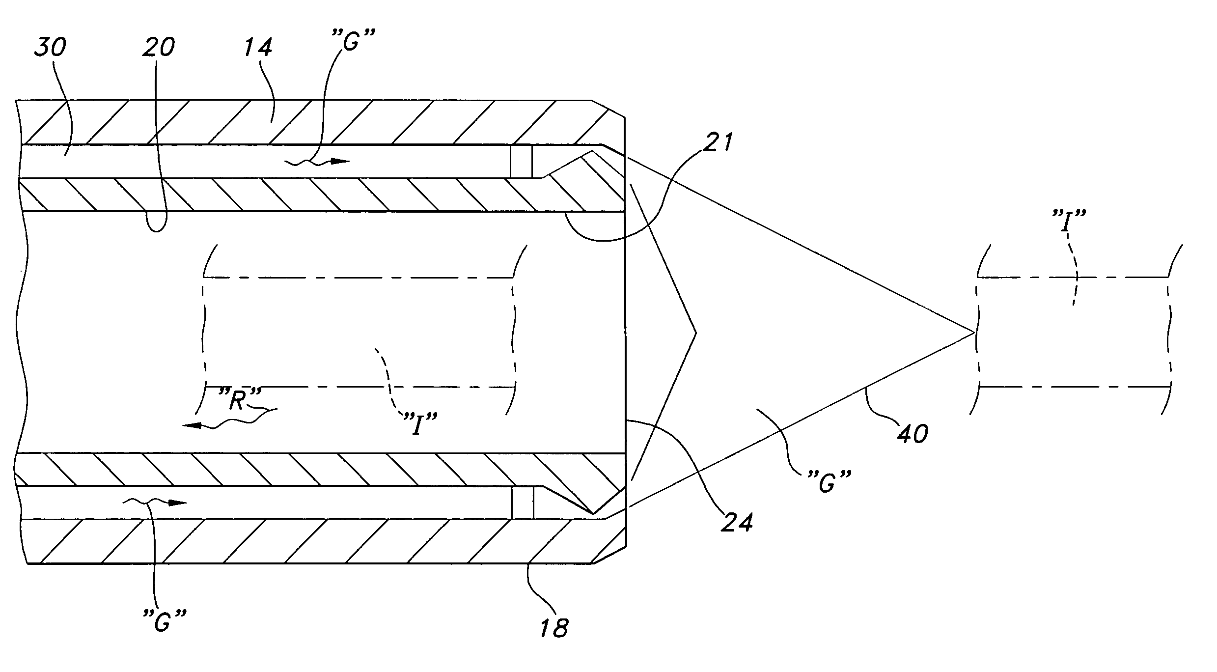
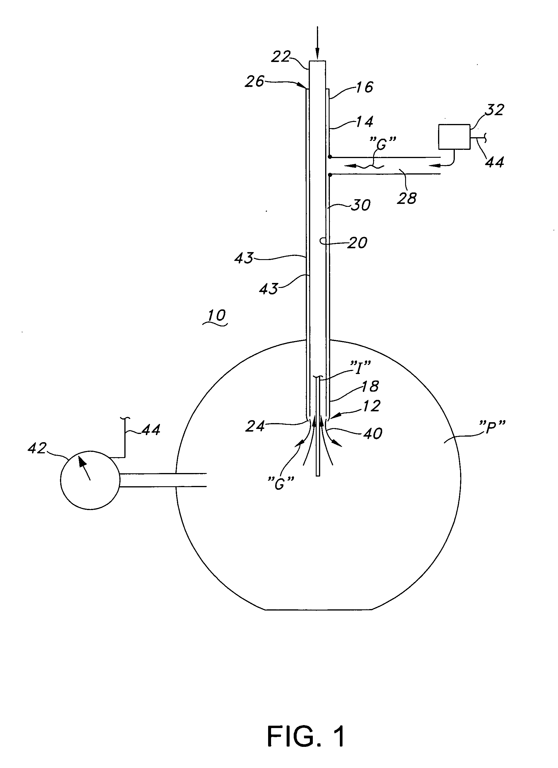
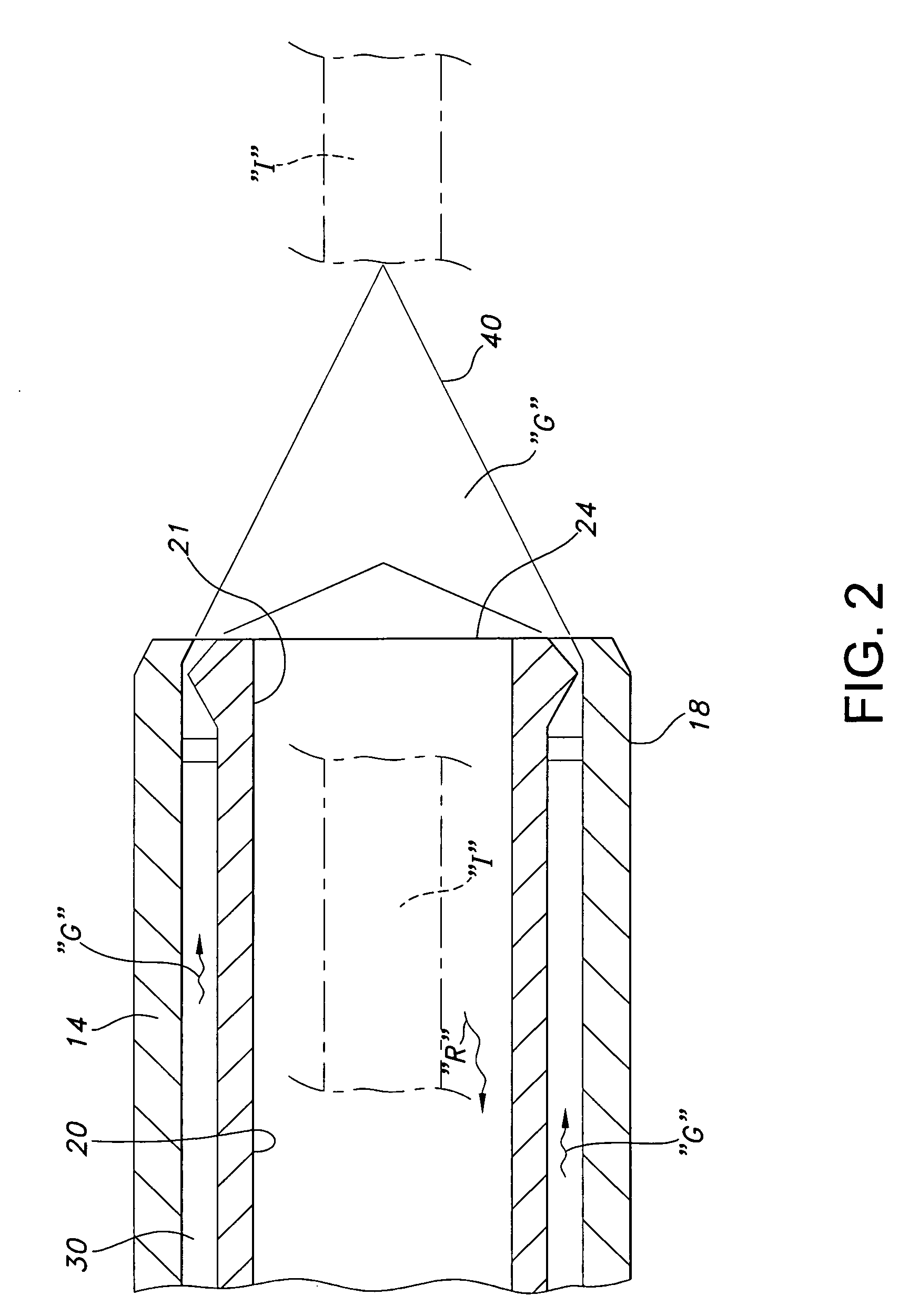
[0039] Referring now to the drawings in detail, and particularly to FIG. 1, there is shown the present invention which comprises a continuous gas flow trocar assembly 10 which provides a completely open aperture 12 for the introduction of a surgical instrument “I” and its access to the peritoneum “P” without any physical contact between the innermost surface of the trocar assembly 10 and the surgical instrument “I” being introduced therewithin or withdrawn therefrom. Use of the trocar assembly 10 would also include the use of an obturator (not shown for clarity) to pierce the patient's abdomen to permit the access into the patient via the trocar assembly 10. The trocar assembly 10 of the present invention comprises an elongated outer tubular member (cannula) 14 having a first or proximal end 16 and a second or distal end 18. The assembly 10 includes an internal tubular member 20, having an open proximal end 22 and an open distalmost end 24, the internal tubular member 20 defining an...


PUM


Abstract

A trocar assembly for providing a pressurized insufflation fluid into a patient cavity and for providing sealable access to the patient cavity by a surgical instrument. The assembly comprises an inner tubular member having a proximal end and a distal end. An outer tubular member is disposed about the inner tubular member, the outer tubular member having a proximal end and a distal end. The distal end of the inner tubular member and the distal end of the outer tubular member define a trocar seal nozzle arranged therebetween.

Description

CROSS-REFERENCE TO RELATED APPLICATIONS [0001] The subject application is a divisional of U.S. patent application Ser. No. 10 / 441,149, filed May 17, 2003, which claims the benefit of priority to U.S. Provisional Application Ser. No. 60 / 461,149, filed Apr. 8, 2003. Each of the foregoing applications is expressly incorporated herein by reference.BACKGROUND OF THE INVENTION [0002] 1. Field of the Invention [0003] The present invention relates to medical devices and more particularly to access devices and particularly their seal arrangements and closure mechanisms applicable to such medical devices. [0004] 2. Prior Art [0005] Laparoscopic surgery is now standard procedure in hospitals today. Abdominal operations are being performed with narrow elongated instruments inserted through small incisions into interior portions of the body. Such laparoscopic procedures are now considered the treatment of choice for operations such as the removal of the gall bladder, spleen, adrenal glands, uter...

Claims


Application Information

Patent Timeline
Patent Type & Authority Applications(United States)
IPC IPC(8): A61M5/178A61B17/00A61B17/34A61B19/00
CPCA61B17/3421A61B17/3423A61B17/3474A61B2017/00265A61B2019/464A61B2090/064
Inventor STUBBS, JACK B.THOMPSON, RONALD J.HARTMAN, GEORGE A. J.HALGREN, DONALD N.CAMPBELL, MICHAEL J.
Owner SURGIQUEST
Why Eureka
Try Eureka